
绘制齿轮 - 圆形和非圆形
4.98/5 (55投票s)
了解齿轮,

引言
DrawInvolute 可用于为特定齿轮找到最佳“废料切口”
探索用于形成齿轮齿廓的渐开线细节
通过使用程序并查看源代码来了解更多关于齿轮的知识
获取切割齿轮毛坯(外圆)、基圆... 的值
在切割渐开线之前,使用本文方法去除齿轮毛坯(圆盘)中的废料:
《大众科学》 - 1961 年 11 月,第 144-148 页
制作木制齿轮?当然,Edwin W. Love 的《制作木制齿轮?方法在这里》已被改编。
用黄色标记的废料切口是渐开线曲线的最佳近似值。
YouTube:使用路由器制作木制齿轮展示了另一种方法。
数据文件和保存的图像可用作插图和齿轮切割模板。
使用超椭圆来制作一些有趣的非圆形齿轮。
背景
我为一个小爱好项目需要几个木制齿轮。在网上搜索,我找到了大量关于齿轮的信息,但关于如何绘制/制作齿轮的代码片段很少,而且没有使用 C# 的,所以我开始收集信息并制作了这个程序 DrawInvolute。
为了解决使用一种方法发现的问题,又添加了更多算法,在完成了圆形齿轮之后,又添加了标准的椭圆形状齿轮,最后是超椭圆非圆形齿轮。
Using the Code
您可以按原样使用该程序来调整齿轮参数并在屏幕上查看结果。
将保存的图像用作插图或木材和其他材料齿轮切割的模板。
如果您想更好地理解某个主题,建议查看源代码。
类名
将 MooreNeighborTracing 算法从 CPP 移植到 C# 以满足我的特殊需求 - 仅内部形状 - 用于清理绘图
添加了 LockBitMap 以提高速度,并添加了 ArrayList 来保存找到点的极坐标表示。
该算法称为 Moore 邻域跟踪。
算法的解释可以在这里找到:http://www.thebigblob.com/moore-neighbor-tracing-algorithm-in-c Erik Smistad
- GearTools,用于转换
rad2deg、inch2mm、pixel2mm以及计算渐开线,处理polarPoint等。 GearParams,用于保存和进行基本的齿轮参数计算。LockBitmap,使用 C# 更快地处理位图 添加了对此程序所需的 16 位支持MooreNeighborTracingEllipse,用于绘制和计算椭圆和超椭圆的函数。BiSection,一个未使用的尝试,用于查找两个齿轮之间的最佳中心距DrawInvoluteTake2,主类,包含drawGear、DrawCenterX、drawMultipageAlignmentGrid、drawTooth、drawRackDrive、drawRackDriven、drawRawTooth、drawIndexMarkNumbers、drawPerfectGear、calcBestMatingGearCenterDistance、drawGearFromArray、fastDrawGearFromArray、drawXaxis、drawCicleMark、makeGearAnimationFromArrayLists... 等函数。
圆形齿轮
GearTools 的渐开线函数用于绘制齿轮齿廓
/// Calculate the involute for a given radius at a given angle adjusting the center to the offset
/// The pf is set to the result
public void involute(bool leftsideoftooth,
	double radius, double rad_angle, PointF offset, ref PointF pf)
{
    pf.X = (float)(radius * (Math.Cos(rad_angle) + (rad_angle * Math.Sin(rad_angle))));
    pf.Y = ((leftsideoftooth == true) ? 1.0f : -1.0f) * (float)(radius *
		(Math.Sin(rad_angle) - (rad_angle * Math.Cos(rad_angle))));
    pf.X += offset.X; pf.Y += offset.Y;
}
使用函数 rotatePoint 来旋转齿廓到其在齿轮上的正确位置
/// Rotate a point around it's offset
public void rotatePoint(PointF offset, double angle, ref PointF p)
{
    float s = (float)Math.Sin(angle);
    float c = (float)Math.Cos(angle);
    // translate point back to origin:
    p.X -= offset.X;
    p.Y -= offset.Y;
    float xnew = p.X * c - p.Y * s;
    float ynew = p.X * s + p.Y * c;
    // translate point back:
     p.X = xnew + offset.X;
     p.Y = ynew + offset.Y;
}
使用渐开线绘制一个齿廓分两步进行 - 首先是齿廓的左侧,然后是右侧。
此处使用 gearParms 类中的齿轮参数。
...
// Draw toolpath left side of tooth
pp.Color = Color.Black;
pp.Width = 0.5f;
for (double angle = -(gp.angle_one_tooth / 4) -
	gp.angle_pitch_tangent; angle < Math.PI * 2; angle += (2 * Math.PI / gp.number_of_teeth))
{
	alpha = 0;
	gt.involute(true, gp.base_radius, alpha, offset, ref from);
	gt.rotatePoint(offset, angle, ref from);
	to = new PointF(0f, 0f);
	for (alpha = 0; alpha < Math.PI / 4; alpha += (Math.PI / 200))
	{
		gt.involute(true, gp.base_radius, alpha, offset, ref to);
		gt.rotatePoint(offset, angle, ref to);
		gr.DrawLine(pp, from, to);
		from = to;
		to.X -= offset.X;
		to.Y -= offset.Y;
		if (Math.Sqrt(to.X * to.X + to.Y * to.Y) > gp.outside_radius)
			break;
	}
}

 // Draw toolpath right side of tooth
for (double angle = (gp.angle_one_tooth / 4) + gp.angle_pitch_tangent;
	angle < Math.PI * 2; angle += (2 * Math.PI / gp.number_of_teeth))
{
	alpha = 0;
	gt.involute(false, gp.base_radius, alpha, offset, ref from);
	gt.rotatePoint(offset, angle, ref from);
	to = new PointF(0f, 0f);
	for (alpha = 0; alpha < Math.PI / 4; alpha += (Math.PI / 200))
	{
		gt.involute(false, gp.base_radius, alpha, offset, ref to);
		gt.rotatePoint(offset, angle, ref to);
		gr.DrawLine(pp, from, to);
		from = to;
		to.X -= offset.X;   // Stop if we passed outside_radius
		to.Y -= offset.Y;
		if (Math.Sqrt(to.X * to.X + to.Y * to.Y) > gp.outside_radius)
			break;
	}
}
...
挑战 1 - 低齿数下的根切
根据互联网上的实验和信息,这仅适用于齿数超过 18 的齿轮,如果齿数少于 18,我们会遇到齿轮制造者称为根切的现象。
根切是指一个齿的尖端切入相邻齿轮的齿根。

为了获得正确的齿廓形状,可以通过将一个直齿条齿轮绕节圆旋转来获得正确的带根切的齿廓。drawRawTooth 通过仅绘制一个齿条齿廓并使用函数 drawSingleToothRack 来实现这一点。
void drawSingleToothRack(ref Graphics gr, PointF Orig_offset, PointF offset,
	ref gearParams gp, double pitchCircleRotateDistance, double rotationAngle)
{
    gearTools gt = new gearTools();
    using (Pen pp = new Pen(Color.Black, 0.25f))
    {
        // Left side of single tooth rack addendum deep
        PointF from_l = new PointF(Orig_offset.X - (float)gp.backlash -
		(float)(gp.addendum * Math.Cos(gp.pressure_angle + Math.PI * 3 / 2)),
		Orig_offset.Y - (float)(gp.addendum));
        PointF to_addendum_l = new PointF(from_l.X + (float)((gp.dedendum + gp.addendum) *
	Math.Cos(gp.pressure_angle + Math.PI * 3 / 2)), from_l.Y + (float)(gp.dedendum + gp.addendum));

        // Move the rack tooth the same distance the pitch circle has rotated
        from_l.X -= (float)pitchCircleRotateDistance;
        to_addendum_l.X -= (float)pitchCircleRotateDistance;

        // Rotate the points found so it keep the right position on the gear
        gt.rotatePoint(offset, rotationAngle, ref from_l);
        gt.rotatePoint(offset, rotationAngle, ref to_addendum_l);

        gr.DrawLine(pp, from_l, to_addendum_l);

        // Right side of single tooth rack addendum deep
        PointF to_r = new PointF(Orig_offset.X + (float)gp.pitch_tooth_width +
	(float)gp.backlash + (float)(gp.addendum * Math.Cos(gp.pressure_angle + Math.PI * 3 / 2)),
	Orig_offset.Y - (float)(gp.addendum));
        PointF to_addendum_r = new PointF(to_r.X - (float)gp.backlash -
	(float)((gp.dedendum + gp.addendum) * Math.Cos(gp.pressure_angle + Math.PI * 3 / 2)),
	to_r.Y + (float)(gp.dedendum + gp.addendum));

        // Move the rack tooth the same distance the pitch circle has rotated
        to_r.X -= (float)pitchCircleRotateDistance;
        to_addendum_r.X -= (float)pitchCircleRotateDistance;

        // Rotate the points found so it keep the right position on the gear
        gt.rotatePoint(offset, rotationAngle, ref to_r);
        gt.rotatePoint(offset, rotationAngle, ref to_addendum_r);

        gr.DrawLine(pp, to_addendum_l, to_addendum_r);
        gr.DrawLine(pp, to_addendum_r, to_r);
    }
}
drawSingleToothRack 在 drawRawTooth 中使用。
// Using a rack with one tooth we can form/remove material between teeth,
// leaving the perfect tooth form
void drawRawTooth(ref Graphics gr, double at_angle, ref gearParams gp, PointF Orig_offset)
{
    // Center the drawing of the rack tooth at the pitch_radius in the midle of the tooth
    PointF offset = new PointF(Orig_offset.X + (float)(gp.pitch_tooth_width / 2),
			Orig_offset.Y + (float)(gp.pitch_radius));
    using (Pen pp = new Pen(Color.Black, 0.1f))
    {
        gearTools gt = new gearTools();
        for (double n = -gp.pitch_tooth_width * 2; n < gp.pitch_tooth_width * 2;
		n += gp.pitch_tooth_width * 4 / 400) // Movement of rack in mm
        {
            double g = Math.PI / 2 + at_angle +
		(Math.PI * 2) / gp.pitch_circle * n; // Movement of the gear
            drawSingleToothRack(ref gr, Orig_offset, offset, ref gp, n, g);
        }
...
drawRawTooth 的使用方法如下,用于绘制多个齿廓。
...
for (double angle = 0.0; angle < Math.PI * 2; angle += Math.PI * 2 / gp.number_of_teeth)
	drawRawTooth(ref gr, angle, ref gp, offset);
...
结果如下:

标准椭圆
使用超椭圆且 n=2,我们可以绘制标准椭圆。
/// Draw Raw Super Ellipse with offset in center
public void drawEllipse_n(Graphics gr, PointF offset, double rotateAngleRadians)
{
    gr.PageUnit = GraphicsUnit.Millimeter;
    float length_perimeter = 0;
    //gr.Clear(Color.White);
    PointF from = new PointF(0, 0);
    PointF to = new PointF(0, 0);
    SizeF size = new SizeF(offset);
    gearTools gt = new gearTools();
    double circular_angle = 0.0;
    // Draw minor axis
    double radius = radiusAtAngleCenter(Math.PI / 2, ref circular_angle);

    using (Pen pp = new Pen(Color.Blue, 0.25f))
    {

        from.X = (float)(0);
        from.Y = (float)(radius);   // At angle PI/2 sin is 1
        from += size;
        to.X = (float)(0);
        to.Y = (float)(-radius);    // At angle 3*PI/2 sin is -1
        to += size;
        gt.rotatePoint(offset, rotateAngleRadians, ref from);
        gt.rotatePoint(offset, rotateAngleRadians, ref to);
        gr.DrawLine(pp, from, to);
    }
        // Draw major axis
    using (Pen pp = new Pen(Color.Green, 0.25f))
    {
        radius = radiusAtAngleCenter(0.0, ref circular_angle);
        from.X = (float)(radius);    // At angle 0.0 cos is 1
        from.Y = (float)(0);
        from += size;
        to.X = (float)(-radius);    // At angle PI cos is -1
        to.Y = (float)(0);
        to += size;
        gt.rotatePoint(offset, rotateAngleRadians, ref from);
        gt.rotatePoint(offset, rotateAngleRadians, ref to);
        gr.DrawLine(pp, from, to);
    }
    double c = Math.Cos(rotateAngleRadians);    // Do rotation calculation without
						// calling a function to speed up
    double s = Math.Sin(rotateAngleRadians);
    double x = 0.0;
    double y = 0.0;
    using (Pen pp = new Pen(Color.Black, 0.25f))
    {
        for (double angle = 0; angle < Math.PI * 2; angle += Math.PI / 1000)
        {
            radius = radiusAtAngleCenter(angle, ref circular_angle);
            x = radius * Math.Cos(circular_angle);      // Use the circular angle - not the warped
						// ellipse angle used to find the length of the radius
            y = radius * Math.Sin(circular_angle);
            to.X = (float)(x * c - y * s);
            to.Y = (float)(x * s + y * c);
            to += size;
            gr.DrawLine(pp, from, to);
            length_perimeter += lengthBetweenPoints(from, to);
            from = to;
        }
        this.perimeter = length_perimeter;
    }
...
MDF 切割出的椭圆齿轮示例
两个标准椭圆驱动齿轮可以与中心销对齐,中心距为 a+b。

两个标准椭圆驱动齿轮和一个中间的从动齿轮可以与焦点销对齐,焦点距为 a+a。


DrawInvolute 如何制作这个?
再次,将一个齿条围绕形状旋转,这次不是围绕圆形,而是围绕椭圆或超椭圆。
为了形成驱动/从动标准椭圆,使用了两个绘制齿条的函数,从动齿条相对于驱动齿条偏移一个齿距。
private void drawRackDrive(Graphics gr, ref gearParams gp, PointF offset,
	int number_of_teeth_in_rack, double rotate_angle, double move_rack)
{
    double ptw = gp.pitch_tooth_width;
    double add = gp.addendum;
    double ded = gp.dedendum;
    PointF from = new PointF();
    PointF to = new PointF();
    PointF s_from = new PointF();
    PointF s_to = new PointF();
    PointF s2_from = new PointF();
    PointF s2_to = new PointF();
    using (Pen pp = new Pen(Color.Black, 0.25f))
    {
        bool first = true;
        int num = number_of_teeth_in_rack / 2;
        float centerX = (float)(offset.X - move_rack + (ptw / 2));
        int cnt = 0;
        for (int n = -num; n < 2; n += 2)
        {
            // Try to minimize number of iteration
            if ((n + 4) * ptw < move_rack)
                continue;
            if (cnt++ > 3)
                break;
            // Draw one tooth
            from.X = (float)(n * ptw + centerX);
            from.Y = offset.Y;
            to.X = from.X - (float)(add * Math.Cos(gp.pressure_angle + Math.PI * 3 / 2));
            to.Y = from.Y - (float)add;
            pp.Color = Color.Black;
            pp.Width = 0.5f;
            {
                gr.DrawLine(pp, rotatePoint(from, offset, rotate_angle),
				rotatePoint(to, offset, rotate_angle));
                s2_from = to;

                if (first == true)
                {
                    first = false;
                }
                else
                {
                    gr.DrawLine(pp, rotatePoint(s2_from, offset, rotate_angle),
				rotatePoint(s2_to, offset, rotate_angle));
                }

                to.X = from.X + (float)(ded * Math.Cos(gp.pressure_angle + Math.PI * 3 / 2));
                to.Y = from.Y + (float)ded;
                gr.DrawLine(pp, rotatePoint(from, offset, rotate_angle),
				rotatePoint(to, offset, rotate_angle));
                s_from = to;

                from.X += (float)ptw;
                to.X = from.X + (float)(add * Math.Cos(gp.pressure_angle + Math.PI * 3 / 2));
                to.Y = from.Y - (float)add;
                gr.DrawLine(pp, rotatePoint(from, offset, rotate_angle),
				rotatePoint(to, offset, rotate_angle));
                s2_to = to;

                to.X = from.X - (float)(ded * Math.Cos(gp.pressure_angle + Math.PI * 3 / 2));
                to.Y = from.Y + (float)ded;
                gr.DrawLine(pp, rotatePoint(from, offset, rotate_angle),
				rotatePoint(to, offset, rotate_angle));
                s_to = to;

                gr.DrawLine(pp, rotatePoint(s_from, offset, rotate_angle),
				rotatePoint(s_to, offset, rotate_angle));
            }
        }
    }
}
从动齿轮的工作方式如下
private void drawRackDriven(Graphics gr, ref gearParams gp, PointF offset,
	int number_of_teeth_in_rack, double rotate_angle, double move_rack)
{
    double ptw = gp.pitch_tooth_width;
    double add = gp.addendum;
    double ded = gp.dedendum;
    PointF from = new PointF();
    PointF to = new PointF();
    PointF s_from = new PointF();
    PointF s_to = new PointF();
    PointF s2_from = new PointF();
    PointF s2_to = new PointF();
    using (Pen pp = new Pen(Color.Black, 0.25f))
    {
        bool first = true;
        int num = number_of_teeth_in_rack / 2;
        float centerX = (float)(offset.X - move_rack - ptw / 2);
        int cnt = 0;
        for (int n = -num; n < 2; n += 2)
        {
            // Try to minimize number of iteration
            if ((n + 2) * ptw < move_rack)
                continue;
            if (cnt++ > 3)
                break;
            // Draw one tooth
            from.X = (float)(n * ptw + centerX);
            from.Y = offset.Y;
            to.X = from.X - (float)(add * Math.Cos(gp.pressure_angle + Math.PI * 3 / 2));
            to.Y = from.Y - (float)add;
            pp.Color = Color.Black;
            pp.Width = 0.5f;
            gr.DrawLine(pp, rotatePoint(from, offset, rotate_angle),
				rotatePoint(to, offset, rotate_angle));
            s2_from = to;

            if (first == true)
            {
                first = false;
            }
            else
            {
                gr.DrawLine(pp, rotatePoint(s2_from, offset, rotate_angle),
				rotatePoint(s2_to, offset, rotate_angle));
            }

            to.X = from.X + (float)(ded * Math.Cos(gp.pressure_angle + Math.PI * 3 / 2));
            to.Y = from.Y + (float)ded;
            gr.DrawLine(pp, rotatePoint(from, offset, rotate_angle),
				rotatePoint(to, offset, rotate_angle));
            s_from = to;

            from.X += (float)ptw;
            to.X = from.X + (float)(add * Math.Cos(gp.pressure_angle + Math.PI * 3 / 2));
            to.Y = from.Y - (float)add;
            gr.DrawLine(pp, rotatePoint(from, offset, rotate_angle),
				rotatePoint(to, offset, rotate_angle));
            s2_to = to;

            to.X = from.X - (float)(ded * Math.Cos(gp.pressure_angle + Math.PI * 3 / 2));
            to.Y = from.Y + (float)ded;
            gr.DrawLine(pp, rotatePoint(from, offset, rotate_angle),
				rotatePoint(to, offset, rotate_angle));
            s_to = to;

            gr.DrawLine(pp, rotatePoint(s_from, offset, rotate_angle),
				rotatePoint(s_to, offset, rotate_angle));
        }
    }
}
标准椭圆只是围绕形状旋转齿条,使用 Ellipse 类中的 angleTangentAtAngle 和 pointAtAngle 函数来定位齿条。
/// The tangent angle on the perimeter at an angle seen from the center
double angleTangentAtAngle(double angleRadians)
{
	double slope_y;
	double x = a * Math.Cos(angleRadians);
	double y = b * Math.Sin(angleRadians);
	// ellipse tangent slope y' = -((b*b*X)/(a*a*Y))
	if (y != 0)      // Avoid divide by zero error
		slope_y = (b * b * x) / (a * a * y);
	else
		slope_y = double.MaxValue;
	return Math.Atan(-slope_y);
}
 /// Point on perimeter at angle seen from center adding a offset
PointF pointAtAngle(double angleRadians, PointF offset)
{
	return new PointF((float)(a * Math.Cos(angleRadians) + offset.X),
		(float)(b * Math.Sin(angleRadians) + offset.Y));
}
...
int cnt = 0;
for (double ang = 0; ang < Math.PI * 2; ang += Math.PI / working_dpi)
{
	cnt++;
	double tangent_angle = el.angleTangentAtAngle(ang);
	center_current_tooth = el.pointAtAngle(ang, Orig_offset);
	// Draw the rack
	//if (cnt <= 600)
	{
		if (ang <= Math.PI)
		{
			if (rbDrive.Checked == true)
			{
				drawRackDrive(gx, ref gp, center_current_tooth,
				(int)(2 * el.perimeter / gp.pitch_tooth_width),
				tangent_angle, -el.lengthAtAngle(ang));
			}
			else
			{
				drawRackDriven(gx, ref gp, center_current_tooth,
				(int)(2 * el.perimeter / gp.pitch_tooth_width),
				tangent_angle, -el.lengthAtAngle(ang));
			}
		}
		else
		{
			if (rbDrive.Checked == true)
			{
				drawRackDrive(gx, ref gp, center_current_tooth,
				(int)(2 * el.perimeter / gp.pitch_tooth_width),
				Math.PI + tangent_angle, -el.lengthAtAngle(ang));
			}
			else
			{
				drawRackDriven(gx, ref gp, center_current_tooth,
				(int)(2 * el.perimeter / gp.pitch_tooth_width),
				Math.PI + tangent_angle, -el.lengthAtAngle(ang));
			}
		}
	}
}
...
挑战 2 - 超椭圆
然而,这种方法对于 n>2 的超椭圆会产生问题,值会跳跃,因此,如果您将角度除以超椭圆公式给出的值,两个点之间的距离可能会很大,这会破坏齿轮的绘制。
解决方案是绘制形状,使用直线填充这些间隙/跳跃,并利用 Moore 邻域跟踪逐像素获取形状,使用这些数据来移动/旋转齿条,我们又能得到一个完美的齿轮。
我尚未解决的一个问题是,如果 n 小于 1,形状是凸形的,齿条会撞到形状中不应该接触的部分。此程序中未实现的解决方案是取一个圆形齿轮,并将其围绕形状滚动。其直径应小于凸形曲率,并进行调整,以便在形状上获得均匀分布的齿。
第一步是获取超椭圆的形状 - 非圆形齿轮
...
using (Graphics gx = Graphics.FromImage((Image)bmp))
{
    gx.Clear(Color.White);
    el.drawRawEllipse_n(gx, Orig_offset, 0.0);
    bmp.Save("super_ellipse.jpg");

    using (tmpbmp = (Bitmap)bmp.Clone())
    {
        Bitmap res_bmp2;
        MooreNeighborTracing mnt = new MooreNeighborTracing();
        if (rbFoci2.Checked == true)
        {
            Orig_offset.X += (float)el.f2;
        }
        res_bmp2 = mnt.doMooreNeighborTracing(ref tmpbmp, Orig_offset, true,
			Orig_offset, ref arrNonCircularShape, working_dpi);
        if (rbFoci2.Checked == true)
        {
            Orig_offset.X -= (float)el.f2;
        }
        res_bmp2.Save("res_non_circular_shape.jpg");
    }

...
下一步是围绕找到的形状旋转一个驱动/从动齿条,以添加齿廓,再次使用 Ellipse 类中的函数。
这次使用这里找到的算法 radiusAtAngleCenter
http://math.stackexchange.com/questions/76099/polar-form-of-a-superellipse
lengthBetweenPoints - 使用勾股定理
tangentAngleAtRadiusAtAngleCenter - 通过找到靠近中点的两个点的割线来计算切线角度。这之前的/之后的导数将更好地近似真实切线,因为一个低估了值,另一个高估了值。
/// Radius of Super Ellipse at angle seen from center
/// http://math.stackexchange.com/questions/76099/polar-form-of-a-superellipse

double radiusAtAngleCenter(double angleRadians, ref double circularAngleRadians)
{
	double c = Math.Cos(angleRadians);
	double s = Math.Sin(angleRadians);
	double cPow = Math.Pow(Math.Abs(c), 2 / n);
	double sPow = Math.Pow(Math.Abs(s), 2 / n);
	double x = a * Math.Sign(c) * cPow;
	double y = b * Math.Sign(s) * sPow;
	double radi = Math.Sqrt(x * x + y * y);
	// See the this as a vector a (x,y) and a std vector (x, 0) the angle
	// between is defined as cos(angle) = a.b/|a||b|
	circularAngleRadians =  Math.Sign(s) * Math.Acos(x / radi);
	if (angleRadians > Math.PI)
		circularAngleRadians = 2 * Math.PI + circularAngleRadians;
	return radi;
}
/// Calculate the length between to points - Using Pythagorean theorem.
float lengthBetweenPoints(PointF from, PointF to)
{
	float x_diff = to.X - from.X;
	float y_diff = to.Y - from.Y;
	return (float)Math.Sqrt(x_diff * x_diff + y_diff * y_diff);
}
/// Calculate tangent angle finding the secant of too points close to the midle point
/// This derivate before/after will make give a better approximation of the
/// real tangent as one underestimate the value and the other overestimate
public double tangentAngleAtRadiusAtAngleCenter(double angleRadians)
{
	double delta_angleRadians = Math.PI / 1000;
	double circle_angle_minus = 0.0;
	double radius_minus = radiusAtAngleCenter(angleRadians - delta_angleRadians,
				ref circle_angle_minus);
	double circle_angle_plus = 0.0;
	double radius_plus = radiusAtAngleCenter(angleRadians + delta_angleRadians,
				ref circle_angle_plus);

	double x_minus = Math.Cos(circle_angle_minus) * radius_minus;
	double y_minus = Math.Sin(circle_angle_minus) * radius_minus;
	double x_plus = Math.Cos(circle_angle_plus) * radius_plus;
	double y_plus = Math.Sin(circle_angle_plus) * radius_plus;
	// The -(Math.PI -  just to adjust to the way i draw the rack at the tangent
	return -(Math.PI - (Math.PI * 4 + Math.Atan2(y_plus - y_minus, x_plus - x_minus)) %
		(Math.PI * 2));
}
...
for (double ang = 0.0; ang < Math.PI * 2; ang += Math.PI / working_dpi)
{
	new_radius = el.radiusAtAngleCenter(ang, ref circleAngle);
	to.X = (float)(new_radius * Math.Cos(circleAngle)) + Orig_offset.X;
	to.Y = (float)(new_radius * Math.Sin(circleAngle)) + Orig_offset.Y;

	center_current_tooth = to;
	len_perimeter += el.lengthBetweenPoints(from, to);
	double tangent_angle = el.tangentAngleAtRadiusAtAngleCenter(ang);
	if (rbDrive.Checked == true)
	{
		drawRackDrive(gx, ref gp, center_current_tooth,
		(int)(2 * el.perimeter / gp.pitch_tooth_width), tangent_angle, -len_perimeter);
	}
	else
	{
		drawRackDriven(gx, ref gp, center_current_tooth,
		(int)(2 * el.perimeter / gp.pitch_tooth_width), tangent_angle, -len_perimeter);
	}
	from = to;
}
...
通过第二次 Moore 邻域跟踪,我们可以看到从中心或焦点看到的带齿廓的齿轮形状。
...
if (rbFoci2.Checked == true)
{
	Orig_offset.X += (float)el.f2;
}
res_bmp = mnt.doMooreNeighborTracing(ref tmpbmp, Orig_offset, true, Orig_offset, ref arrGear, working_dpi);
...
现在可以根据 Moore 邻域跟踪找到的 arrGear 来绘制齿轮,使用函数 drawGearFromArrayListWithCenterAt 且不进行旋转。
现在,它将矢量坐标保存为 SVG 格式,存储在名为 filename 的 html 文件中。还添加了一个小的 JavaScript,用于以不同尺寸显示齿轮。
SVG 部分的数据可以用作 3D/CNC 的输入来生成齿轮。还生成了一些 ruby 脚本文件,可用作 Google Sketchup 的扩展。
private void drawGearFromArrayListWithCenterAt(Graphics gr, ref ArrayList arrGear,
	double rotateGearAroundCenterRadians, PointF offset, Pen pp, String filename)
{
    gr.PageUnit = GraphicsUnit.Millimeter;
    float minX = float.MaxValue;
    float maxX = float.MinValue;
    float minY = float.MaxValue;
    float maxY = float.MinValue;
    SizeF move_center = new SizeF(offset);
    PointF centerGear = new PointF(0, 0);
    PointF to = new PointF(0, 0);
    PointF [] newPol = new PointF[arrGear.Count];
    PointF[] rawPol = new PointF[arrGear.Count];
    int cnt = 0;
    if (rotateGearAroundCenterRadians == 0.0)
    {
        foreach (polarPoint pol in arrGear)
        {
            to.X = (float)pol.x;
            to.Y = (float)pol.y;
            rawPol[cnt] = to;
            minX = Math.Min(to.X, minX);
            minY = Math.Min(to.Y, minY);
            maxX = Math.Max(to.X, maxX);
            maxY = Math.Max(to.Y, maxY);
            to += move_center;
            newPol[cnt++] = to;
        }
    }
    else
    {
        double c = Math.Cos(rotateGearAroundCenterRadians);
        double s = Math.Sin(rotateGearAroundCenterRadians);

        foreach (polarPoint pol in arrGear)
        {
            to.X = (float)(pol.x * c - pol.y * s);
            to.Y = (float)(pol.x * s + pol.y * c);
            rawPol[cnt] = to;
            minX = Math.Min(to.X, minX);
            minY = Math.Min(to.Y, minY);
            maxX = Math.Max(to.X, maxX);
            maxY = Math.Max(to.Y, maxY);
            to += move_center;
            newPol[cnt++] = to;
        }
    }
    if (newPol.Count() > 2)
    {
        gr.DrawLines(pp, newPol);
        float width = maxX - minX + 1;
        float height = maxY - minY + 1;

        StringBuilder sb = new StringBuilder();
        gearTools gt = new gearTools();
        ... SVG and java script is added to the sb with appendline here ...
        System.IO.StreamWriter file = new System.IO.StreamWriter(filename);
        file.WriteLine(sb.ToString());
        file.Close();
    }
}
SVG 看起来像这样
<svg width="1209px" height="1184px" viewBox="-598 -586 1209 1184">
<g id="superellipse" style="stroke: black; fill: none;">
<path d="M 0 0
L 0 0
L 599 0
L 599 -1
...
L 599 2
L 599 1
L 599 0
"/>
</g>
<!--<use xlink:href="#superellipse" transform="scale(0.03)"/>-->
</svg>
JavaScript 部分如下
<script language="javescript" type="text/javascript">
<!-- Hide javascript
    var myVar = setInterval(myTimer, 10);
    var value = 1.0;
    function myTimer()
    {
        var d = new Date();
        value -= 0.001;
        var my_str = "value: " + value + "<br/>";
        if (value < 0.11)
        {
           clearInterval(myVar);
        }
        var scale_str = "scale(" + String(value) + ")";
        document.getElementById("superellipse").setAttribute("transform", scale_str);
     }
 -->
 </script>
 <noscript>
 <h3>JavaScript needed</h3>
 </noscript>
请自行承担使用风险,见下文。
Google Sketchup 的 ruby 脚本是根据此处代码制作的。
将其中一个文件以 .rb 扩展名保存在 Sketchup 的插件文件夹中。
启动 Sketchup 并选择扩展 draw_gear。
所有 .rb 文件都使用相同的扩展名,因此如果您想在一次演示中使用更多文件,则需要在文件中修改名称。
函数中的点数已受限,因为如果扩展有 10000 多个点,Sketchup 就会崩溃。
因此,请确保在尝试使用 draw_gear 扩展之前保存您的工作。
    ...
    	sb_ruby.AppendLine("#On Windows, the plugins are installed here:\n" +
					   "#C:\\Users\\\\AppData\\Roaming\\SketchUp\\
						SketchUp [n]\\SketchUp\\Plugins\n" +
					   "#Save this file as draw_gear.rb here...
						start sketchup and select extension draw_gear\n\n" +
					   "# First we pull in the standard API hooks.\n" +
						"require 'sketchup.rb'\n" +

						"# Show the Ruby Console at startup so we can\n" +
						"# see any programming errors we may make.\n" +
						"SKETCHUP_CONSOLE.show\n" +

						"# Add a menu item to launch our plugin.\n" +
						"UI.menu(\"Plugins\").add_item(\"Draw gear\") {\n" +
						"  UI.messagebox(\"I'm about to draw a gear in mm!\") \n" +

						"  # Call our new method.\n" +
						"  draw_gear\n" +
						"}\n" +
						"def draw_gear\n" +
						"# Get \"handles\" to our model and the
						Entities collection it contains.\n" +
						"model = Sketchup.active_model\n" +
						"entities = model.entities\n" +
						"gpt = []\n");
	foreach (PointF polElem in rawPol)
	{
		if (idx++ >= -1)
			if (idx%10 == 0)
				sb_ruby.AppendLine(String.Format("gpt[{0}] = [{1}, {2}, 0 ]",
				idx/10 , (polElem.X/25.4f).ToString(CultureInfo.GetCultureInfo("en-GB")),
				(polElem.Y/25.4f).ToString(CultureInfo.GetCultureInfo("en-GB"))));
	}
	sb_ruby.AppendLine("  # Add the face to the entities in the model\n" +
					   "  face = entities.add_face(gpt)\n\n" +
					   "  # Draw a circle on the ground plane around the origin.\n" +
					   "  center_point = Geom::Point3d.new(0,0,0)\n" +
					   "  normal_vector = Geom::Vector3d.new(0,0,1)\n" +
					   "  radius = 0.1574803\n" +
					   "  edgearray = entities.add_circle center_point,
						normal_vector, radius\n" +
					   "  first_edge = edgearray[0]\n" +
					   "  arccurve = first_edge.curve\n" +
					   "  face.pushpull 0.3937\n" +
					   "  view = Sketchup.active_model.active_view\n" +
					   "  new_view = view.zoom_extents\n");
	sb_ruby.AppendLine("end");


	System.IO.StreamWriter file2 = new System.IO.StreamWriter(filename.Replace(".html", ".rb"));
	file2.WriteLine(sb_ruby.ToString());
	file2.Close();
}
挑战 3 - 计算啮合齿轮
第一步是使用不带齿廓的形状,并将其围绕形状外部的新点进行旋转。
如果旋转,一个完整的圆周和围绕新点的形状周长长度与不带齿廓的形状的周长长度相同,我们就会获得与普通圆形齿轮相同的行为 - 它们在节圆/形状上无滑动地旋转。
这可以看作是无齿廓的形状是一个凸轮,而啮合形状是凸轮从动件点的位置。
drawBestMatingGearCenterDistance2 为我们执行此操作并返回一个新 arrGear 来表示啮合齿轮。
drawBestMatingGearCenterDistance2(ref arrNonCircularShape, ref arrGear, ref E);
计算最佳中心距
我们首先找到非圆形形状无滑动旋转的最佳新点。
这里重要的一点是闭合形状,否则 perimeterLength 总是相同的,最后一个跳跃是必需的。
private double calculateBestCenterDistance(ref ArrayList arrNonCircularShape,
	double a, double e, double n)
{
	//rtbCalcBestCenter.Text = "";
	int number_of_revolutions = Convert.ToInt32(tbNoRevolutions.Text);
	double centerOffset = Convert.ToDouble(tbCenterOffset.Text);
	double E = a * (1 + Math.Sqrt(1 + ((n * n) - 1) * (1 - e * e)));
	rtbCalcBestCenter.AppendText("E calculated: " + E.ToString());
	double new_radius = 0.0;
	double deltaAngle = 0.0;
	double prevAngle = 0.0;
	double rotateMatingGear = 0.0;
	double currentMatingAngle = 0.0;
	double E_offset = 10.0;
	double E_step = 4;
	int last_hit = 0;

	int cnt = 0;
	polarPoint pol = (polarPoint)arrNonCircularShape[1];
	double lastX = pol.x;
	double lastY = pol.y;
	double perimeterLength = 0.0;
	double checkLength = 0.0;
	foreach (polarPoint polP in arrNonCircularShape)
	{
		if (++cnt > 2) // Skip first point in array it has no correct radius
		{
			perimeterLength += Math.Sqrt((polP.x - lastX) * (polP.x - lastX) +
						(polP.y - lastY) * (polP.y - lastY));
			lastX = polP.x;
			lastY = polP.y;
		}
	}
	checkLength = perimeterLength * number_of_revolutions;
	double nextX = 0;
	double nextY = 0;
	double firstX = 0;
	double firstY = 0;
	for (int loop_cnt = 0; loop_cnt < 100; loop_cnt++)  // Brute force way of getting best value..
	{
		currentMatingAngle = 0.0;
		perimeterLength = 0.0;

		E = a * (1 + Math.Sqrt(1 + ((n * n) - 1) * (1 - e * e))) + E_offset;
		if (E > 0)
		{

			for (int rev = 0; rev < number_of_revolutions; rev++)
			{
				cnt = 0;
				pol = (polarPoint)arrNonCircularShape[1];
				new_radius = E - pol.radius;
				firstX = lastX = (Math.Cos(currentMatingAngle) * new_radius);
				firstY = lastY = (Math.Sin(currentMatingAngle) * new_radius);
				foreach (polarPoint polP in arrNonCircularShape)
				{
					if (++cnt > 2) 	// Skip first point in array it has
							//no correct radius
					{
						new_radius = E - polP.radius;
						deltaAngle = Math.Abs(prevAngle - polP.angle);
						rotateMatingGear = deltaAngle *
						(polP.radius / new_radius);    // rotate other way the
								// minus, on the other side PI,
								// number of revolution times
						currentMatingAngle += rotateMatingGear;

						nextX = (Math.Cos(currentMatingAngle) * new_radius);
						nextY = (Math.Sin(currentMatingAngle) * new_radius);
						perimeterLength += Math.Sqrt((nextX - lastX) *
						(nextX - lastX) + (nextY - lastY) * (nextY - lastY));
						lastX = nextX;
						lastY = nextY;
					}
					prevAngle = polP.angle;
				}
			}
		}
		perimeterLength += Math.Sqrt((firstX - lastX) * (firstX - lastX) + (firstY - lastY) *
			(firstY - lastY));    // Close the shape..
		// Suspect a better way of finding the best value can be done
		// (binary search like - recurcive) but this works and don't take long time
		// so for now it's the way I'm doing it.
		if ((perimeterLength < checkLength) || (currentMatingAngle > (Math.PI * 2)))
		{
			if (last_hit == 1)
				E_step *= 1.2;      // Works better than 2.0 for some reason
			else
				E_step /= 3;
			E_offset += E_step;
			last_hit = 1;
		}
		else
		{
			if (last_hit == -1)
				E_step *= 1.2;      // Works better than 2.0 for some reason
			else
				E_step /= 5;
			E_offset -= E_step;
			last_hit = -1;
		}
	}
	...
为啮合齿轮添加齿廓
有了这个中心距,很容易将原始带齿廓的齿轮围绕啮合齿轮旋转以给它添加齿廓,fastDrawGearFromaArrayListWithCenterAt 只绘制了原始齿轮与啮合齿轮接触的部分,速度提高了 6 倍。
仅绘制数据量的六分之一可以再提高 6 倍的速度,我看不出区别,而且产生的齿轮对我来说可以正常工作。
...
foreach (polarPoint polP in arrNonCircularShape)
{
	calcAngle = polP.angle;
	if (++cnt > 2) // Skip first point in array it has no correct radius
	{
		{
			new_radius = E - polP.radius;
			deltaAngle = Math.Abs(prevAngle - calcAngle);
			rotateNonCircularShapeRadians = (calcAngle * (new_radius / polP.radius)) %
							(Math.PI * 2);
			rotateMatingGear = ((deltaAngle) * (polP.radius / new_radius));    // rotate
				// other way the minus, on the other side PI, number of revolution times
			currentMatingAngle += rotateMatingGear;
			centerNonCircularShape.X = (float)(Math.Cos(currentMatingAngle) * E);
			centerNonCircularShape.Y = (float)(Math.Sin(currentMatingAngle) * E);
			centerNonCircularShape += moveToOffset;
			if (cnt % 6 == 0)       // Minimize the number of drawings
			{
				//drawGearFromaArrayListWithCenterAt(ref gr, ref arrGear,
				//(3 * Math.PI + (-polP.angle + currentMatingAngle)) % (Math.PI * 2),
				//centerNonCircularShape, pp);
				fastDrawGearFromaArrayListWithCenterAt(ref gr, ref arrGear,
				(3 * Math.PI + (-polP.angle + currentMatingAngle)) % (Math.PI * 2),
				-polP.angle, centerNonCircularShape, pp);
			}
		}
	}
	prevAngle = calcAngle;

}
...
结果齿轮的动画
为了更好地展示结果齿轮,添加了一个动画,结果的 html 保存在一个名为 animation.html 的文件中,并在程序中使用浏览器控件显示,我发现这默认使用 IE 7,但通过将此行插入 html 的 head 部分,它可以在我的计算机上运行 SVG 和 JavaScript。
sb.AppendLine(" <meta http-equiv=\"X-UA-Compatible\" content=\"IE=edge\">\"");
完整的函数如下
   private void makeGearAnimationFromArrayLists( ref ArrayList arrGearNonCircular,
	ref ArrayList arrGear, ref ArrayList arrGearMating, ref double E, String filename,
	ref Ellipse el, ref gearParams gp)
        {
            MinMax minmax = new MinMax();
            MinMax minmaxMating = new MinMax();
            PointF centerGear = new PointF(0, 0);
            PointF to = new PointF(0, 0);
            PointF[] matingPol = new PointF[arrGearMating.Count];
            PointF[] origPol = new PointF[arrGear.Count];
            // Find min and max X and Y values to optimize height/width and viewport of animation
            int cnt = 0;
            foreach (polarPoint pol in arrGear)
            {
                to.X = (float)pol.x;
                to.Y = (float)pol.y;
                origPol[cnt++] = to;
                minmax.setMinMax(to);
            }
            // Both gears min and max are needed
            cnt = 0;
            foreach (polarPoint pol in arrGearMating)
            {
                to.X = (float)pol.x;
                to.Y = (float)pol.y;
                matingPol[cnt++] = to;
                minmaxMating.setMinMax(to);
            }
            if (origPol.Count() > 2)
            {
                float width = (float)(Math.Max(minmax.maxX, minmaxMating.maxX) -
				Math.Min(minmax.minX, minmaxMating.minX)) * 2 + 1;
                float height = (float)(Math.Max(Math.Max(minmax.maxX, minmaxMating.maxX),
				Math.Max(minmax.maxY, minmaxMating.maxY)) -
				Math.Min(Math.Min(minmax.minX, minmaxMating.minX),
				Math.Min(minmax.minY, minmaxMating.minY)))  + 1;

                StringBuilder sb = new StringBuilder();
                StringBuilder sbGear = new StringBuilder();
                gearTools gt = new gearTools();
                // Insert html header and make it show gear parameters
                sb.AppendLine("<HTML>");
                sb.AppendLine("<head>");
                // webbrowser used to display the animation, defaults to IE7,
                // this tell it to use a never version with support for the SVG and Java Script used
                sb.AppendLine("
                <meta http-equiv=\"X-UA-Compatible\"
                content=\"IE=edge\">\"");
                sb.AppendLine("</head>");
                sb.AppendLine("<H2><B>" + "a=" +
                el.a.ToString().PadRight(6).Substring(0, 6) +
                                        " b=" +
                                        el.b.ToString().PadRight(6).Substring(0, 6) +
                                        " n=" +
                                        el.n.ToString().PadRight(6).Substring(0, 6) +
                                        " revs=" +
                                        tbNoRevolutions.Text.PadRight(3).Substring(0, 3) +
                                        " ptw=" +
                                        gp.pitch_tooth_width.ToString().
						PadRight(6).Substring(0, 6) +
                                        " foci=" + rbFoci2.Checked.ToString());
                sb.AppendLine(" add=" + gp.addendum.ToString().PadRight(10).Substring(0, 10) +
                              " ded=" + gp.dedendum.ToString().PadRight(10).Substring(0, 10) +
                              " E=" + E.ToString().PadRight(10).Substring(0, 10) +
                              ((rbDrive.Checked == true) ? " Drive" :
                              " Driven") + "</H2></B>>" );
                // The SVG stuff used to draw gear and mating gear
                sb.Append(String.Format("<svg width=\"{0}px\" height=\"{1}px\"
			viewBox=\"{2} {3} {4} {5}\">\n",
                    gt.mm2Pixel(width / 4, working_dpi),
                    gt.mm2Pixel(height / 4, working_dpi),
                    gt.mm2Pixel(Math.Min(minmax.minX, minmaxMating.minX) / 4, working_dpi),
                    gt.mm2Pixel(Math.Min(Math.Min(minmax.minX, minmaxMating.minX),
			Math.Min(minmax.minY, minmaxMating.minY)) / 4, working_dpi),
                    gt.mm2Pixel((width + (float)E) / 4, working_dpi),
                    gt.mm2Pixel(height / 4, working_dpi)));
                // Here goes the first gear
                sb.Append("<g id=\"superellipse\"
                style=\"stroke: black; fill: red;\">\n");
                sb.AppendLine(String.Format("<path d=\"M {0} {1} ",
		gt.mm2Pixel(origPol[0].X, working_dpi), gt.mm2Pixel(origPol[0].Y, working_dpi)));
                foreach (PointF polElem in origPol)
                {
                    sb.AppendLine(String.Format("L {0} {1} ",
                    gt.mm2Pixel(polElem.X, working_dpi),
			gt.mm2Pixel(polElem.Y, working_dpi)));
                }
                sb.AppendLine("\"/>\n</g>");

                // Here goet the mating gear
                sb.Append("<g id=\"mating\"
                style=\"stroke: black; fill: blue;\">\n");
                sb.AppendLine(String.Format("<path d=\"M {0} {1} ",
                gt.mm2Pixel(origPol[0].X,
			working_dpi), gt.mm2Pixel(origPol[0].Y, working_dpi)));
                foreach (PointF polElem in matingPol)
                {
                    sb.AppendLine(String.Format("L {0} {1} ",
                    gt.mm2Pixel(polElem.X, working_dpi),
			gt.mm2Pixel(polElem.Y, working_dpi)));
                }
                sb.AppendLine("\"/>\n</g>");

                sb.AppendLine("<!--<use xlink:href=\"#superellipse\"
                transform=\"scale(0.03)\"/>-->");
                sb.AppendLine("</svg>");
                // End of the SVG and start of the JavaScript to animate the gears
                sb.AppendLine("<script language=\"javescript\"
                type=\"text/javascript\">");
                sb.AppendLine("<!-- Hide javascript");
                // If more revolutions -> more data points so I speed up the animation
		// to get an even speed for the all animations
                sb.AppendLine(String.Format("var myVar = setInterval(myTimer, {0});",
			30 / Convert.ToDouble(tbNoRevolutions.Text)));
                sb.AppendLine("var value = 0.0;");
                sb.AppendLine("var rotate = 0.0;");
                sb.AppendLine("var cnt = 0;");
                sb.AppendLine("function myTimer() {");
                sb.AppendLine("    var d = new Date();");
                // Array of rotation step values for the mating gear
                sb.Append("    steps = [ ");
                // To keep things in sync a second array controls the original gear
                sbGear.Append("    stepsGear = [ ");
                // MooreNeighbor start at 360 and goes to 0 degree
                double startDegree = 360;
                double prevMatingDegree = startDegree;
                double matingDegree = 0.0;

                cnt = 0;
                int cntDegreeEntrys = 0;
                double deltaAngle = 0.0;

                foreach (polarPoint pol in arrGearNonCircular)
                {
                    if (cnt++ > 2)
                        if (pol.angle_degree < startDegree)
                        {
                            cntDegreeEntrys++;
                            deltaAngle = Math.Abs(prevMatingDegree - pol.angle_degree);
                            startDegree -=  1 / Convert.ToDouble(tbNoRevolutions.Text);
                            matingDegree = deltaAngle * (pol.radius / (E - pol.radius));
                            // Rotate the mating gear this increment
                            sb.Append(matingDegree.ToString().Replace(',','.') + ", ");
                            // and the original gear this and the gear run in sync.
                            sbGear.Append(deltaAngle.ToString().Replace(',', '.') + ", ");
                            prevMatingDegree = pol.angle_degree;
                        }
                }
                // End the arrays with a value not used..
                sb.AppendLine(" 0];" );
                sbGear.AppendLine(" 0];");
                // Insert second array into script
                sb.AppendLine(sbGear.ToString());
                // Reset the animation after all entrys have been shown once,
		// keeps things in sync to avoid a small error to add up to a bigger one
                sb.AppendLine(String.Format("    if (cnt > {0})", cntDegreeEntrys));
                sb.AppendLine("    {");
                sb.AppendLine("       cnt = 0;");
                sb.AppendLine("       value = 0.0;");
                sb.AppendLine("       rotate = 0.0;");
                sb.AppendLine("    }");
                // Mating rotate one way the original the other -/+
                sb.AppendLine("    rotate -= steps[cnt];");
                sb.AppendLine("    value += stepsGear[cnt++];");
                // Changing the scale factor the translate has to be changed too
		// ex. 312 with 0.25 will be 561 with 0.45 scale
                // We have to start the animation at 180 degree if foci is used - Move the
		// mating gear to it's correct position at E/(1/scalefactor)
                if (rbFoci2.Checked == false)
                    sb.AppendLine(String.Format("	   var scale_str = \"translate({0},0)
			scale(0.25) rotate(\" + String(rotate) + \")\";",
			gt.mm2Pixel((float)E / 4, working_dpi)));
                else
                    sb.AppendLine(String.Format("	   var scale_str = \"translate({0},0)
			scale(0.25) rotate(\" + String(rotate+180) + \")\";",
			gt.mm2Pixel((float)E / 4, working_dpi)));
                sb.AppendLine("    document.getElementById(\"superellipse\").setAttribute
                (\"transform\", scale_str);");
                // Remember to scale this too
                sb.AppendLine("    var scale_str2 = \"scale(0.25)
                rotate(\" + String(value) + \")\";");
                sb.AppendLine("    document.getElementById
                (\"mating\").setAttribute(\"transform\",
			scale_str2);");

                sb.AppendLine("}");
                sb.AppendLine("-->");
                sb.AppendLine("</script>");
                sb.AppendLine("<noscript>");
                sb.AppendLine(" <h3>JavaScript needed</h3>");
                sb.AppendLine("</noscript>");
                sb.AppendLine("</HTML>");

                // Save the animation html file - so it can be used outside the program
                System.IO.StreamWriter file = new System.IO.StreamWriter(filename);
                file.WriteLine(sb.ToString());
                file.Close();

                // Get the fullpath location of the amination html to be shown using webbrowser
                var myAssembly = System.Reflection.Assembly.GetEntryAssembly();
                var myAssemblyLocation = System.IO.Path.GetDirectoryName(myAssembly.Location);
                var myHtmlPath = Path.Combine(myAssemblyLocation, filename);
                Uri uri = new Uri(myHtmlPath);
                webBrowser1.ScriptErrorsSuppressed = false;
                webBrowser1.Navigate(uri);
                webBrowser1.Focus();
                webBrowser1.SetBounds(0, 0, 1400, 1000);
                webBrowser1.Show();
                // Show a button to stop the webbrowser and return to programs normal mode
                bHideAnimation.Show();
            }
        }
动画屏幕看起来像这样

使用“隐藏动画”按钮后,会显示如下屏幕(图片使用了不同的值)。
最终超椭圆结果
进行 Moore 邻域跟踪,并绘制找到的 arrGear,我们就有两个有趣的齿轮可以玩了。

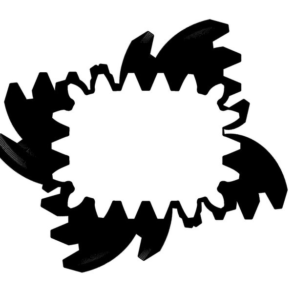
MDF 切割的方齿轮

程序保存的文件
按钮 calc
带有废料切口数据的文件的文件:DrawInvoluteValues.txt 和 DrawInvoluteValuesBest.txt
生成许多文件名类似于:gear_2.66 _9.548_77.88_93.57_63.51_18.jpg 的文件
具有 3-96 个齿。
- gear_
- 模数
- 模块
- 基圆半径
- 外圆半径
- 起始滚动位置
- 齿数
gear_5 _5.08 _6.906_11.68_18.28_3 .jpg

gear_5 _5.08 _39.13_47.24_33.71_17 .jpg

gear_5 _5.08 _41.43_49.78_33.78_18 .jpg

按钮 Ellipse
- Moore 邻域 traceres_ellipse.jpg - 椭圆之后
- ellipse_drive.jpg - 带有中心/焦点标记和椭圆的最终驱动椭圆
- ellipse_driven.jpg - 带有中心/焦点标记和椭圆的最终从动椭圆
按钮 Superellipse
super_ellipse.jpg - 仅超椭圆

res_before_moore.jpg - 齿条围绕超椭圆旋转后
res_non_circular_shape.jpg - Moore 邻域跟踪后的超椭圆,用于获取 polarPoint 的 arrayList

res_super_ellipse.jpg - Moore 邻域跟踪后
super_ellipse_drive.jpg - 添加了中心/焦点标记、参数详细信息和超椭圆后的最终驱动超椭圆
super_ellipse_driven.jpg - 添加了中心/焦点标记、参数详细信息和超椭圆后的最终从动超椭圆

rawMatingGear.jpg - 围绕最佳中心距旋转 res_super_ellipse 后

res_mating_super_ellipse.jpg - 带有中心标记和参数详细信息的最终啮合超椭圆

历史
第一个版本...
第二个版本 v2
更多评论提到 GDI+ 和内存问题,程序错误地尝试使用 dispose 和 GC.collect 来修复,可以通过以下方式解决:
所有临时的动态分配的 GDI 相关对象,如 Brush、Pen、GraphicsPath、Matrix,都应通过 using 语句进行控制,例如:
using(var path = new GraphicsPath())
{
// Do your stuff
}
感谢提供的宝贵建议 - 效果很好。
另一个要求是提供矢量输出以供 3D 打印机/CNC 使用
现在已通过 SVG 输出和小型 JavaScript 实现,该 JavaScript 可将齿轮缩小以显示为不同尺寸,请查看运行程序时所在的 html 文件。
修复了一些小错误。
第三个版本 v3
“Super ellipse”按钮现在在计算超椭圆和啮合齿轮后显示动画。使用“Hide animation”按钮停止/关闭动画。
还添加了一个实验性的 draw_gear ruby 脚本扩展/插件,用于 Google Sketchup。在加载大型齿轮后,我的 Sketchup 崩溃了,我尝试限制点数,但为安全起见:在您自行承担风险尝试之前,请保存您的工作!
剩余挑战 - 待办
加载一个具有中心点(作为文件名的一部分)的闭合形状图像的函数,围绕此点滚动一个圆形齿轮,并使啮合齿轮围绕中心点旋转
在形状内旋转齿轮,如行星齿轮,可能通过反向旋转齿轮来生成啮合齿轮来实现
此实验代码包含在源代码中,它似乎适用于圆形齿轮,也应该适用于一些椭圆。
在将其在程序中启用之前,需要进行更多调查。
有关数学问题和解决方案的更多详细信息,请参阅书籍
Litvin、Fuetes-Aznar、Gonzalez-Perez 和 Hayasaka 的《非圆形齿轮设计与生成》
/// <summary>
/// Experimental works with ordinary circular gears - planatary gears see rawMatingGear.jpg
/// Ellipse with center - you get pointy teeth
/// Ellipse with foci - not working - Noncircular Gears Design and Generation by Litvin,
/// Fuetes-Aznar, Gonzalez-Perez and Hayasaka mention you will need 3 ellipses with
/// center at foci stacked to do this.
/// </summary>
/// <param name="arrNonCircularShape"></param>
/// <param name="arrGear"></param>
/// <param name="E"></param>
/// <returns></returns>
private double drawBestMatingGearCenterDistanceOutside(ref ArrayList arrNonCircularShape,
	ref ArrayList arrGear, ref double E)
{
	int pixelHeight = 0;
	int pixelWidth = 0;
	Stopwatch sw = new Stopwatch();
	PointF offset = new PointF(0, 0);
	gearParams gp = new gearParams();
	gp.setInitValues(Convert.ToDouble(tbDiametralPitch.Text),
	Convert.ToDouble(tbTeeth.Text), (float)Convert.ToDouble(tbPinSize.Text),
	(float)Convert.ToDouble(tbToolWidth.Text), Convert.ToDouble(tbPressureAngle.Text),
	Convert.ToDouble(tbBacklash.Text), cbColor.Checked);
	gp.calc();

	// Draw mating shape we got from new center
	Ellipse el = new Ellipse(Convert.ToDouble(tbEllipse_a.Text),
		Convert.ToDouble(tbEllipse_b.Text), Convert.ToDouble(tbEllipse_n.Text));
	//double Enear = calculateBestCenterDistanceNearCalculated(ref arrNonCircularShape,
	//el.a, el.e, el.n);
	if (rbFoci2.Checked == true)
	{
		offset.X -= (float)el.f1;
	}
	E = calculateBestCenterDistance(ref arrNonCircularShape, el.a, el.e, el.n);

	//double Eold = calculateBestCenterDistance();

	//rtbCalcBestCenter.AppendText("E: " + E.ToString().PadRight(10).Substring(0, 10) +
	//" Eold: " + Eold.ToString().PadRight(10).Substring(0, 10) + "\n");
	//E = Math.Min(E, Eold);
	//E -= 0.5;
	rtbCalcBestCenter.AppendText("Using E: " + E.ToString().PadRight(10).Substring(0, 10) + "\n");
	Bitmap bmp; // Must have same number of pixels in x,y for drawing multipage alignment
			// grid correct
	// MooreNeighborTrace only work on even pixels cnt
	int pixels = gp.mm2Pixel((float)((E + 10 + gp.addendum + gp.dedendum) * 4), working_dpi);
	if (pixels % 2 == 1)
		pixels++;
	bmp = new Bitmap(pixels, pixels, System.Drawing.Imaging.PixelFormat.Format16bppRgb555);
	bmp.SetResolution(working_dpi, working_dpi);
	Graphics gr = Graphics.FromImage((Image)bmp);

	gr.PageUnit = GraphicsUnit.Millimeter;
	gr.Clear(Color.White);
	int number_of_revolutions = Convert.ToInt32(tbNoRevolutions.Text);
	double newRadius = 0.0;
	double rotateMatingGear = 0.0;
	PointF centerNonCircularShape = new PointF(0, 0);
	PointF centerMatingGear = offset;
	offset.X = (float)(E + 10 + gp.addendum + gp.dedendum) *2;
	offset.Y = offset.X;
	SizeF moveToOffset = new SizeF(offset);
	double calcAngle = 0.0;
	PointF from = new PointF(0, 0);
	using (Pen pp = new Pen(Color.Black, 0.5f))
	{
		double prevAngle = 0.0;
		double prevRadius = 0.0;
		double currentMatingAngle = 0.0;
		double deltaAngle = 0.0;


		int cnt = 0;
		sw.Start();
		for (double rev = 0; rev < number_of_revolutions; rev++)
		{
			prevAngle = 0.0;
			currentMatingAngle = (rev * 2 * Math.PI) / (double)number_of_revolutions;
			cnt = 0;
			foreach (polarPoint polP in arrNonCircularShape)
			{
				calcAngle = polP.angle;

				if (++cnt > 2) // Skip first point in array it has no correct radius
				{
					//if (cnt % 50 == 0) // Limit number of drawings
					{
						newRadius = E + polP.radius;
						deltaAngle = Math.Abs(prevAngle - calcAngle);
						rotateMatingGear = ((deltaAngle) *
						(newRadius / prevRadius));    // rotate other way the
						//minus, on the other side PI, number of revolution times
						currentMatingAngle -= rotateMatingGear;
						centerNonCircularShape.X = (float)(Math.Cos
								(currentMatingAngle) * E);
						centerNonCircularShape.Y = (float)(Math.Sin
								(currentMatingAngle) * E);
						centerNonCircularShape += moveToOffset;
						if (cnt % 6 == 0)       // Minimize the number of
									// drawings
						{

							//drawGearFromaArrayListWithCenterAt
							//(ref gr, ref arrGear, (3 * Math.PI +
							//(-polP.angle + currentMatingAngle)) %
							//(Math.PI * 2), centerNonCircularShape, pp);
							fastDrawGearFromaArrayListWithCenterAt(ref gr,
							ref arrGear, (3 * Math.PI + (-polP.angle -
							currentMatingAngle)) % (Math.PI * 2),
							-polP.angle, centerNonCircularShape, pp);
						}
					}
				}
				prevAngle = calcAngle;
				prevRadius = E + polP.radius;
			}
		}
	}
	sw.Stop();
	rtbCalcBestCenter.AppendText("Draw Mating:  " + sw.ElapsedMilliseconds.ToString().PadLeft(4) +
		" ms\n");
	bmp.Save("1037482/rawMatingGear.jpg");

	Bitmap res_bmp;
	MooreNeighborTracing mnt = new MooreNeighborTracing();
	arrGear.Clear();

	sw.Restart();
	using (res_bmp = mnt.doMooreNeighborTracing(ref bmp, offset, true, offset,
				ref arrGear, working_dpi))
	{
		sw.Stop();
		rtbCalcBestCenter.AppendText("Second Moore: " +
			sw.ElapsedMilliseconds.ToString().PadLeft(4) + " ms\n");
		gp.getPixelHeightWidthOffsetFromPolarPoints(ref arrGear, working_dpi,
				ref pixelHeight, ref pixelWidth, ref offset);
		using (Bitmap bmpSecond = new Bitmap(pixelWidth, pixelHeight,
				System.Drawing.Imaging.PixelFormat.Format16bppRgb555))
		{
			bmpSecond.SetResolution(working_dpi, working_dpi);
			using (Graphics gx = Graphics.FromImage((Image)bmpSecond))
			{

				gx.PageUnit = GraphicsUnit.Millimeter;

				using (Pen pp = new Pen(Color.Black, 0.5f))
				{
					if (rbFoci2.Checked == true)
					{
						offset.X += (float)(el.f1);
						if (Convert.ToDouble(tbNoRevolutions.Text) == 2)
						{
							offset.X += (float)(el.f2);
						}
					}
					gx.Clear(Color.White);
					drawGearFromArrayListWithCenterAt(gx, ref arrGear,
						0.0, offset, pp, "res_mating_super_ellipse.html");
					drawCenterX(gx, offset);

					gx.DrawString("a=" + el.a.ToString().PadRight(6).Substring(0, 6) +
						" b=" + el.b.ToString().PadRight(6).Substring(0, 6) +
						" n=" + el.n.ToString().PadRight(6).Substring(0, 6) +
						" revs=" + tbNoRevolutions.Text.PadRight(3).
						Substring(0, 3) +
						" ptw=" + gp.pitch_tooth_width.ToString().
						PadRight(6).Substring(0, 6) +
						" foci=" + rbFoci2.Checked.ToString()
						, new Font("Tahoma", 8), Brushes.Black,
						new PointF(10, 0));
					gx.DrawString("E=" + E.ToString().PadRight(10).
						Substring(0, 10) +
						" DP=" + gp.diametral_pitch.ToString().
						PadRight(10).Substring(0, 10) +
						" add=" + gp.addendum.ToString().
						PadRight(10).Substring(0, 10) +
						" ded=" + gp.dedendum.ToString().
						PadRight(10).Substring(0, 10)
						, new Font("Tahoma", 8), Brushes.Black,
							new PointF(10, 4));
					bmpSecond.Save("1037482/res_mating_super_ellipse.jpg");
				}
			}
		}
	}
	return 0.0;
}