
读取 12 段 LED 显示屏的数字
为 Raspberry Pi 开发显示屏读取器。

引言
本文介绍了作者为检测刀具设定器上 12 段 LED 显示屏的数字而编写的软件
背景
我们公司正在运行生产数控机床。设置时,我们需要输入每种刀具的尺寸。为了测量这些尺寸,我们使用一家德国公司 Zoller 的旧式刀具设定器。尺寸显示在刀具设定器的 LED 显示屏上。以前,我们将这些尺寸写在纸上,然后输入到不同的机器中。
这个过程既慢又乏味,而且容易出错。我想要一个可以自动化这个过程的东西,于是就想到了使用带有摄像头模块的树莓派。它足够小,可以放在显示屏前面读取数字。这个项目中最难的部分当然是分析图片的软件。我在这方面花了一些功夫,并认为分享出来是个好主意。
使用代码
代码中最重要的部分是 ZollerImage 类,所有分析都在其中进行。为了开发这个类,我创建了一个简单的 GUI,可以在其中加载图像,设置一些值,并显示中间结果。我在 NetBeans 中完成了所有工作,源代码可在上方下载。这个项目包含两个包。displayAnalyzer 包包含图像分析部分,gui 包包含 GUI 部分。它还包含一些测试图像,也在下载链接中。
要使用它,只需从 NetBeans 或您喜欢的 IDE 运行它,然后点击 文件-打开,然后选择“Testimages”文件夹中的一个示例文件。图像应显示在窗口左侧的 JavaFX ImageView 中。按“分析”按钮,读取结果将发送到 system.out 并显示在两个结果标签中。右侧的文本字段选择上方行中的一个数字位置。包含此数字的图像显示在右侧的 ImageView 中。我在调试时使用了右侧的 ImageView。我想尝试 Google Guava 库中的 eventbus,所以我实现了一个 ImageEvent 类,用于将图像从分析部分发送到 GUI 部分。这是 ImageEvent 类
package se.mecona.zollerDisplayAnalyzer.gui;

import java.awt.image.BufferedImage;

/**
 * Class for image event used to send intermediate images from the analysis
 * to display them in the left or right views in the gui.
 * @author Mats
 */
public class ImageEvent {

    /**
     * The view to show the image in. LEFT or RIGHT
     */
    public enum selectedImageView {

        /**
         * Selects the LEFT view for the image
         */
        LEFT,

        /**
         * Selects the RIGHT view for the image
         */
        RIGHT };
    private final selectedImageView selectedView;
    private final BufferedImage image;

    /**
     * Constructor for the ImageEvent class. Takes the view to show the image in
     * and the image as parameters.
     * @param selectedView  The view to show the image in. LEFT or RIGHT
     * @param image         The image to show
     */
    public ImageEvent(selectedImageView selectedView, BufferedImage image) {
        this.selectedView = selectedView;
        this.image = image;
    }

    /**
     *
     * @return the selected image view, LEFT or RIGHT
     */
    public selectedImageView getSelectedView() {
        return selectedView;
    }

    /**
     *
     * @return the image
     */
    public BufferedImage getImage() {
        return image;
    }
}
这样就可以轻松地从代码中的任何位置发送任何图像了
Globals.getEventBus().post( new ImageEvent(ImageEvent.imageType.RIGHT, image));
其中图像的类型是 BufferedImage。Globals 类是一个单例,仅包含 eventBus。这是 Google Guava 的唯一用途。通过删除对 Globals 类和 ImageEvent 类的任何引用,可以轻松地将其从 displayAnalyzer 包中移除。
分析步骤
分析分几个步骤进行,我在这里尝试解释一下。
首先,图像从磁盘加载到 GUI 创建的 imageTester 类的对象中。
通过按下“分析”按钮启动分析过程。阈值从 UI 中的滑块设置。UI 中显示的数字也从文本字段设置。
调用 imageTester.analyze 来启动分析。然后 imageTester 对象创建一个 ZollerImage 类的对象,该对象执行实际工作。
    /**
     * Analyzes the image contained in this object, if it exists.
     * Stores the result internally
     */
    public void analyze() {
        if (image != null) {
            ZollerImage zollerImage = new ZollerImage(image);
            zollerImage.setThreshold(threshold);
            zollerImage.setDigitToShow(digitToShow);

            zollerImage.analyze(ZollerImage.AnalyzeRow.BOTH);

            upperDigits = zollerImage.getDigits(AnalyzeRow.UPPER);
            System.out.println("Upper digits = " + upperDigits);

            lowerDigits = zollerImage.getDigits(AnalyzeRow.LOWER);
            System.out.println("Lower digits = " + lowerDigits);
        }
    }
zollerImage 对象首先通过应用阈值操作来准备图像,以清理图像。它仅在绿色通道中进行,因为显示屏主要是绿色的。
然后检查图像的哪个部分将被分析。我这样做是为了节省时间,如果只需要两个数字中的一个。分析是通过 AnalyzeDigitRow 方法对图像的一半进行一次。
在原始图像中,数字略微倾斜。通过执行剪切操作使它们变直。
现在将图像裁剪掉数字周围的黑色区域。这是过程中的一个重要部分。我必须考虑数字之间的间距。我们需要在左右两侧各保存一小部分,其宽度等于间距宽度的一半。如果我们不这样做,然后将剩余的图像分成九个部分(每个数字一个),我们就无法将数字放在九个子图像的中间。为了解决这个问题,我使用了一个常量 PADDING_DIVISOR。我取亮区的宽度,除以 PADDING_DIVISOR,然后得到应该添加到左右两侧的像素列数。
例如,如果亮区宽度为 644 像素,PADDING_DIVISOR 为 50,则我们在左侧和右侧各添加 644/50 = 12 像素。
由于第一个位置始终有一个字母(测试图像中的 X 或 Z),最后一个位置始终有一个数字,因此我们知道这些位置始终是亮的。这使得事情更容易,因为我们总是知道图像中有多少个数字(或者说符号)位置。
但是还有一个额外的问题。最后一个数字可能是“1”。由于此显示屏有 12 段,数字“1”的段不是最右边的段,而是中间的段。我们必须考虑到这一点,因此我们在 checkIfLastDigitIsOne 方法中对此进行了额外检查。在此方法中,我们检查此数字位置中亮部的宽度。如果它小于总宽度的三分之一,我们就认为它必须是“1”,并且图像会被重新裁剪,右侧会增加一些区域。这个额外的宽度由 PADDING_FRACTION_FOR_LAST_DIGIT_1 常量设置。
所有这些都在 getNonEmptyPart 方法中处理。
    /**
     * Method that returns the non empty part of the image.
     * @param image             The original image
     * @param paddingFraction   The fraction of the image width that is used as spacing between the digits
     * @param addExtraFraction  The fraction of the image width that is used for extra padding if last digit is a "1"
     * @return a new image that contains the part of the image that has digits.
     */
    public static BufferedImage getNonEmptyPart(BufferedImage image, int paddingFraction, int addExtraFraction) {
        // Get first non empty column
        int startCol = getNonEmptyCol(image, 0, 1);

        int width = getNonEmptyCol(image, image.getWidth() - 1, -1) - startCol;
        int padding;
        if (paddingFraction == 0) {
            padding = 0;
        } else {
            padding = width / paddingFraction;
        }

        int addExtraFractionPadding;
        if (addExtraFraction == 0) {
            addExtraFractionPadding = 0;
        } else {
            addExtraFractionPadding = width / addExtraFraction;
        }

        if (startCol < padding) {
            throw new IllegalArgumentException("padding too big for image left");
        }
        if (startCol + padding + addExtraFractionPadding + width > image.getWidth()) {
            throw new IllegalArgumentException("padding too big for image right");
        }

        image = image.getSubimage(startCol - padding, 0, width + 2 * padding + addExtraFractionPadding, image.getHeight());

        int startRow = getNonEmptyRow(image, 0, 1);

        int height = getNonEmptyRow(image, image.getHeight() - 1, -1) - startRow;

        image = image.getSubimage(0, startRow, image.getWidth(), height);
        //Globals.getEventBus().post( new ImageEvent(ImageEvent.imageType.RIGHT, image));
        return image;
    }
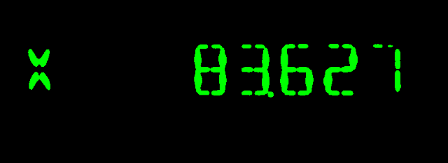
现在我们的图像看起来像这样:

既然已经获得了数字区域,我们就可以开始分析每个数字位置了。这在 analyzeDigitImage 方法中完成。这个显示屏中有一些特殊位置。第一个位置始终是一个字母,表示测量轴。我们不关心这个,所以我们只是忽略它并存储 NO_DIGIT 常量。
下一个位置始终是符号位置。对于这个,我们只需要看到数字区域是否有任何亮像素,因为没有加号。只有在数字为负数时才有减号。
包含小数点的位置始终是第 5 位。为此,我们将包含点的区域设置为黑色,这样它就不会干扰段分析。我将宽度分成四部分,高度分成八部分,并将最低的右侧 1/4 x 1/8 部分设置为黑色。
最后,是时候查看每个数字的不同段了。首先,我们去除数字周围的黑色空白部分。然后我们可以查看剩余部分的宽度。如果它很窄,那么数字就是“1”。这个检查在 isOne 方法中完成。否则,我们继续并查看段。
如果我们像这样给段编号
     -- 2 -- -- 7 --
    |       |       |
    |       |       |
    0       5      10
    |       |       |
    |       |       |
     -- 3 -- -- 8 --
    |       |       |
    |       |       |
    1       6      11
    |       |       |
    |       |       |
     -- 4 -- -- 9 --
并稍加思考,我们就会得到不同数字的以下唯一模式。
    1 - already detected
    2 - 0 and 11 empty
    3 - 0 and 1 empty
    4 - 1 and 2-7 empty
    5 - 1 and 10 empty
    6 - 10 empty
    7 - 0, 1 and 3-8 empty
    8 - none empty
    9 - 1 empty
    0 - 3-8 empty
结果是我们只需要查看 6 个不同的段。为此,我们将数字图像垂直分成八部分,水平分成三部分。
                colStart    colEnd     rowStart     rowEnd
    Area 0      0          1/3         1/8         3/8
    Area 1      0          1/3         5/8         7/8
    Area 10     2/3        3/3         1/8         3/8
    Area 11     2/3        3/3         5/8         7/8
    Area 2-7    1/3        2/3         0           2/8
    Area 3-8    1/3        2/3         3/8         5/8
这是在 analyzeSegments 方法中完成的。
    /**
     * Performs an analysis of the bright parts of an image containing just one
     * digit.
     * @param digitImage The digit image to analyze
     * @return an int representing the image found.
     */
    private int analyzeSegments(BufferedImage digitImage) {
        // First remove black space around the image.

        digitImage = ImageAnalyzer.getNonEmptyPart(digitImage, 0,0);

        /*
        These are the segments for the different digits.
        Possible digits:
        1 - already detected
        2 - 0 and 11 empty
        3 - 0 and 1 empty
        4 - 1 and 2-7 empty
        5 - 1 and 10 empty
        6 - 10 empty
        7 - 0, 1 and 3-8 empty
        8 - none empty
        9 - 1 empty
        0 - 3-8 empty
         -- 2 -- -- 7 --
        |       |       |
        |       |       |
        0       5      10
        |       |       |
        |       |       |
         -- 3 -- -- 8 --
        |       |       |
        |       |       |
        1       6      11
        |       |       |
        |       |       |
         -- 4 -- -- 9 --

        6 areas to analyze.
        We split the digit image in eight parts vertically and tree parts horisontally.
                    colStart    colEnd     rowStart     rowEnd
        Area 0      0          1/3         1/8         3/8
        Area 1      0          1/3         5/8         7/8
        Area 10     2/3        3/3         1/8         3/8
        Area 11     2/3        3/3         5/8         7/8
        Area 2-7    1/3        2/3         0           2/8
        Area 3-8    1/3        2/3         3/8         5/8
         */
        //             Areas   :   0  1  10 11 27 38
        final boolean[][] areas = {{true, true, true, true, true, false}, // digit 0
        {false, false, false, false, true, true}, // 1
        {false, true, true, false, true, true}, // 2
        {false, false, true, true, true, true}, // 3
        {true, false, true, true, false, true}, // 4
        {true, false, false, true, true, true}, // 5
        {true, true, false, true, true, true}, // 6
        {false, false, true, true, true, false}, // 7
        {true, true, true, true, true, true}, // 8
        {true, false, true, true, true, true}};// 9
        final int[] colStart = {0, 0, 2, 2, 1, 1}; // Start column for area
        final int[] rowStart = {1, 5, 1, 5, 0, 3}; // Start row for area


        boolean[] filledArea = new boolean[6];
        for (int i = 0; i < 6; i++) {
            filledArea[i] = scanArea(colStart[i], rowStart[i], digitImage );
        }

        // Now scan the filled areas to find out which digit it is.
        int thisDigit = NO_DIGIT;
        for (int i = 0; i <= 9; i++) {
            if (isThisDigit(areas[i], filledArea)) {
                thisDigit = i;
                break;
            }
        }
        return thisDigit;
    }
之后,我们应该就能得到正确的数字了。这是我的分析算法的第二版。第一版出现了一些错误的读数。我没有进行统计,但错误率远低于 1%。在这个版本中,我添加了一种报告读取错误的方法,但到目前为止,经过几周的使用,我还没有发现任何错误。希望这种情况会继续下去,但以前我注意到,由于一年中的不同时间,建筑物的光照条件略有不同,所以我已经调整了几次曝光。
第二版的主要区别在于我利用了数字的位置。符号和小数点总是在同一位置,这似乎使算法更加可靠。
树莓派注意事项
在 GUI 中有一个“运行测试”按钮,它会运行一系列测试图像的分析器代码,以确保任何更改都不会破坏检测。这段代码中的很多内容包含硬编码的目录和其他不良习惯。displayAnalyzer 包应该更干净。这是在树莓派应用程序中使用的一部分。我所做的只是删除了 eventbus 部分(见上文)。树莓派应用程序包含拍摄显示屏图像、分析数字并生成可以传输到我们不同数控机的代码文件的代码。它还有一个报告错误读数的按钮。它会存储有问题的图像,以便我根据需要改进算法。
我几乎所有的代码都是在 Windows 机器上使用 NetBeans 开发的。唯一在树莓派上完成的部分是使用摄像头的代码,这主要是一个 bash 脚本。在 Windows 机器上构建的 .jar 文件只是复制到树莓派中并按原样执行。
致谢
IOResult 类来自 Almas Baimagambetov 关于 JavaFX 编程出色的 YouTube 频道。我从他那里学到了很多。