
Intel® Quark™ Microcontroller D2000 - 加速计教程
此示例应用程序读取加速度计数据并将其输出到串行端口,同时使用 Intel® 集成性能基元微控制器库(DSP 函数)计算最后 15 个 Z 轴读数的均方根、方差和平均值。
获取新的 Intel® 物联网开发者套件,这是一个完整的软硬件解决方案,使开发人员能够使用 Intel® Galileo 和 Intel® Edison 主板创建令人兴奋的新解决方案。请访问 Intel® 物联网开发者中心。
Intel® System Studio for Microcontrollers 包含多个示例,可帮助您快速掌握其基本功能并熟悉 Intel® Quark™ Microcontroller Software Interface (Intel® QMSI)。此示例应用程序读取加速度计数据并将其输出到串行端口,同时使用 Intel® 集成性能基元微控制器库(DSP 函数)计算最后 15 个 Z 轴读数的均方根、方差和平均值。
要求
- 请确保您已完成“入门”说明,可在以下位置找到: https://software.intel.com/en-us/iot/hardware/d2000/get-started
- Intel® Quark™ Microcontroller D2000 开发板和 USB 数据线
- Intel ® System Studio for Microcontrollers
- FTDI 数据线(TTL-232R-3V3 型号效果很好)用于串行输出。您可以购买 FTDI 数据线,或在此处了解更多信息: http://www.ftdichip.com/Products/Cables/USBTTLSerial.htm。该页面顶部的链接允许您下载 FTDI 数据线的驱动程序(如果需要)。
说明
- 通过以下配置连接 FTDI 数据线进行串行输出:
- 将串行数据线的 GND(黑色)连接到主板的 GND 引脚。
- 将串行数据线的 TXD(橙色)连接到主板的 RX 引脚。
- 将串行数据线的 RXD(黄色)连接到主板的 TX 引脚。

- 启动 Intel ® System Studio for Microcontrollers IDE。
- 使用“加速度计”示例项目文件创建一个项目,如下所示:
- 从 **文件** 菜单中,选择 **新建**,然后选择 **Intel Project for Microcontrollers**。此时会显示“创建新项目”向导。
- 在“创建新项目”向导中指定以下值:
- 开发板: **Intel® Quark™ D2000 Developer Board**
- 项目类型: **Intel® QMSI (1.1)**
- 连接类型: **USB-Onboard**
- 项目名称: **Accelerometer**
- 点击 **完成。**

- 设置串行终端视图以查看传感器输出。此窗口将通过串行数据线通过 UART 接口显示加速度计的传感器数据。
提示: 端口会因使用的串行硬件而异,并且可能列出多个端口。有几种方法可以检查您的端口。
注意: 如果关闭了“串行终端”窗口,可以通过选择 **窗口 > 显示视图 > 其他 > Intel ISSM > 串行终端** 重新打开它。
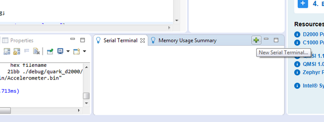
- 在窗口的右下角,选择“串行终端”选项卡,然后点击
 图标以打开新的串行终端连接。
- 确保已选择正确的串行端口。您还可以点击“自定义配置”菜单来修改默认的串行连接设置。

- 断开 FTDI 数据线与 PC 的连接,并刷新“打开串行终端”窗口以确定哪个 COM 端口是活动的。
- Linux*:使用 ‘dmesg’ 命令查看端口状态。
- Windows*:打开设备管理器查看端口(COM 和 LPT)状态。
- 点击 **确定**,串行终端的连接即建立。您应该在串行控制台中看到“已连接”状态。
- 在窗口的右下角,选择“串行终端”选项卡,然后点击
- 构建并部署您的项目。
注意: 您也可以部署和调试。从 **调试**
 下拉列表中,选择“Accelerometer (flashing)”。
- 在“项目浏览器”中选择“Accelerometer”项目。
- 点击 **构建**
 按钮来编译您的项目。
 - 从 **运行**
 下拉列表中,选择“Accelerometer (flashing)”。
 - 在终端中查看加速度计的 X、Y 和 Z 值。
工作原理
加速度计示例使用板载 Bosch BMC150 加速度计,该加速度计通过 I2C 接口连接到微控制器,并使用 Intel® Quark™ 微控制器中集成的 RTC(实时时钟)。它还使用集成的 UART 模块通过串行端口输出数据。
示例从 main 函数开始,在 rtc 配置结构中设置 RTC 参数。
      /* Configure the RTC and request the IRQ. */
      rtc.init_val = 0;
      rtc.alarm_en = true;
      rtc.alarm_val = INTERVAL;
      rtc.callback = accel_callback;
      rtc.callback_data = NULL;
此配置启用了 RTC 警报,并将 accel_callback 设置为 RTC 警报的回调函数。它用于定期打印加速度计数据。
接下来,代码使用 QMSI API 调用请求 RTC 中断,并启用 RTC 时钟。
      qm_irq_request(QM_IRQ_RTC_0, qm_rtc_isr_0);

      /* Enable the RTC. */
      clk_periph_enable(CLK_PERIPH_RTC_REGISTER | CLK_PERIPH_CLK);
之后,它根据加速度计类型(BMC150 或 BMI160)配置加速度计参数。
#if (QUARK_D2000)
      cfg.pos = BMC150_J14_POS_0;
#endif /* QUARK_D2000 */

       /* Initialise the sensor config and set the mode. */
      bmx1xx_init(cfg);
      bmx1xx_accel_set_mode(BMX1XX_MODE_2G);

#if (BMC150_SENSOR)
       bmx1xx_set_bandwidth(BMC150_BANDWIDTH_64MS); /* Set the bandwidth. */
#elif(BMI160_SENSOR)
       bmx1xx_set_bandwidth(BMI160_BANDWIDTH_10MS); /* Set the bandwidth. */
#endif /* BMC150_SENSOR */
cfs.pos 参数用于配置 BMC150 加速度计的加速度计地址。Intel® Quark™ Microcontroller D2000 Developer Kit 主板有一个跳线,允许更改地址。BMC150_J14_POS_0 是默认(无跳线,I2C 地址 0x10)配置。
接下来,设置 RTC 配置,从而启用 RTC 警报。
       /* Start the RTC. */
      qm_rtc_set_config(QM_RTC_0, &rtc);
使用 while 循环等待读取并打印到串行控制台输出的定义数量的加速度计样本。
       /* Wait for the correct number of samples to be read. */
       while (!complete)
       ;
每次达到 125 毫秒间隔并触发 RTC 警报时,都会调用以下 accel_callback 函数。在函数开头定义的 accel 数据结构被传递到 bmx1xx_read_accel 函数中,该函数用当前读取的加速度计数据填充它。如果读取成功,则将加速度计数据打印到串行控制台输出;否则,打印错误消息。
/* Accel callback will run every time the RTC alarm triggers. */
static void accel_callback(void *data)
{
       bmx1xx_accel_t accel = {0};

       if (0 == bmx1xx_read_accel(&accel)) {
              QM_PRINTF("x %d y %d z %d\n", accel.x, accel.y, accel.z);
       } else {
              QM_PUTS("Error: unable to read from sensor");
       }
如果启用了 IPP(在示例应用程序中默认启用),它将通过调用 print_axis_stats 函数打印 Z 轴的统计信息。(请参阅下面的 print_axis_stats 函数说明。)
#if (__IPP_ENABLED__)
       print_axis_stats(accel.z);
#endif /* __IPP_ENABLE__ */
回调函数检查是否已读取定义的样本数量;如果没有,则重置 RTC 警报并递增计数,否则将 complete 变量设置为 true。
       /* Reset the RTC alarm to fire again if necessary. */
       if (cb_count < NUM_SAMPLES) {
              qm_rtc_set_alarm(QM_RTC_0,
                            (QM_RTC[QM_RTC_0].rtc_ccvr + INTERVAL));
              cb_count++;
       } else {
              complete = true;
       }
请注意,默认情况下,该应用程序在退出前读取 500 个样本(NUM_SAMPLES)。
最后,当 complete 变量设置为 true 时,while 循环退出,应用程序将最终语句打印到串行控制台输出,然后退出。
       QM_PUTS("Finished: Accelerometer example app");

       return 0;
}
Intel® 集成性能基元微控制器库
Intel® 集成性能基元微控制器库是一系列用于 x86 微控制器的信号和数据处理应用程序的构建模块。Intel® IPP 提供 Intel® IPP 经典样式 API 和通用 DSP 样式 API;此应用程序使用 DSP 样式 API 开发,以演示 Intel® IPP for Microcontrollers 在 DSP 用例中的用法。有关 Intel® IPP 的更多信息,请参阅 Intel® System Studio for Microcontrollers 用户和参考指南。
print_axis_stats 函数使用 Intel IPP(Intel® 集成性能基元)库打印最后 15 个(由 NUM_SAMPLES 设置)Z 轴读数的统计信息。
首先,它使用新的 Z 轴样本更新 samples 数组,并在需要时更新样本计数。
static void print_axis_stats(int16_t value)
{
       static uint32_t index = 0;
       static uint32_t count = 0;
       float32_t mean, var, rms;

       /* Overwrite the oldest sample in the array. */
       samples[index] = value;
       /* Move the index on the next position, wrap around if necessary. */
       index = (index + 1) % SAMPLES_SIZE;

       /* Store number of samples until it reaches SAMPLES_SIZE. */
       count = count == SAMPLES_SIZE ? SAMPLES_SIZE : count + 1;
接下来,它使用 ippsq 统计函数计算并打印收集样本的均方根、方差和平均值。
/* Get the root mean square (RMS), variance and mean. */
       ippsq_rms_f32(samples, count, &rms);
       ippsq_var_f32(samples, count, &var);
       ippsq_mean_f32(samples, count, &mean);

       QM_PRINTF("rms %d var %d mean %d\n", (int)rms, (int)var, (int)mean);
}
加速度计示例应用程序代码
/*
* Copyright (c) 2016, Intel Corporation
* All rights reserved.
*/

/*
* QMSI Accelerometer app example.
*
* This app will read the accelerometer data from the onboard BMC150/160 sensor
* and print it to the console every 125 milliseconds. The app will complete
* once it has read 500 samples.
*
* If the app is compiled with the Intel(R) Integrated Performance Primitives
* (IPP) library enabled, it will also print the Root Mean Square (RMS),
* variance and mean of the last 15 samples each time.
*/

#include
#if (__IPP_ENABLED__)
#include
#endif
#include "clk.h"
#include "qm_interrupt.h"
#include "qm_isr.h"
#include "qm_rtc.h"
#include "qm_uart.h"
#include "bmx1xx/bmx1xx.h"

#define INTERVAL (QM_RTC_ALARM_SECOND >> 3) /* 125 milliseconds. */
#define NUM_SAMPLES (500)
#if (__IPP_ENABLED__)
/* Number of samples to use to generate the statistics from. */
#define SAMPLES_SIZE (15)
#endif /* __IPP_ENABLED__ */

static volatile uint32_t cb_count = 0;
static volatile bool complete = false;

#if (__IPP_ENABLED__)
static float32_t samples[SAMPLES_SIZE];

static void print_axis_stats(int16_t value)
{
      static uint32_t index = 0;
      static uint32_t count = 0;
      float32_t mean, var, rms;

      /* Overwrite the oldest sample in the array. */
      samples[index] = value;
      /* Move the index on the next position, wrap around if necessary. */
      index = (index + 1) % SAMPLES_SIZE;

      /* Store number of samples until it reaches SAMPLES_SIZE. */
      count = count == SAMPLES_SIZE ? SAMPLES_SIZE : count + 1;

      /* Get the root mean square (RMS), variance and mean. */
      ippsq_rms_f32(samples, count, &rms);
      ippsq_var_f32(samples, count, &var);
      ippsq_mean_f32(samples, count, &mean);

      QM_PRINTF("rms %d var %d mean %d\n", (int)rms, (int)var, (int)mean);
}
#endif /* __IPP_ENABLE__ */

/* Accel callback will run every time the RTC alarm triggers. */
static void accel_callback(void *data)
{
      bmx1xx_accel_t accel = {0};

      if (0 == bmx1xx_read_accel(&accel)) {
            QM_PRINTF("x %d y %d z %d\n", accel.x, accel.y, accel.z);
      } else {
            QM_PUTS("Error: unable to read from sensor");
      }

#if (__IPP_ENABLED__)
      print_axis_stats(accel.z);
#endif /* __IPP_ENABLE__ */

      /* Reset the RTC alarm to fire again if necessary. */
      if (cb_count < NUM_SAMPLES) {
            qm_rtc_set_alarm(QM_RTC_0,
                        (QM_RTC[QM_RTC_0].rtc_ccvr + INTERVAL));
            cb_count++;
      } else {
            complete = true;
      }
}

int main(void)
{
      qm_rtc_config_t rtc;
      bmx1xx_setup_config_t cfg;

      QM_PUTS("Starting: Accelerometer example app");

      /* Configure the RTC and request the IRQ. */
      rtc.init_val = 0;
      rtc.alarm_en = true;
      rtc.alarm_val = INTERVAL;
      rtc.callback = accel_callback;
      rtc.callback_data = NULL;

      qm_irq_request(QM_IRQ_RTC_0, qm_rtc_isr_0);

      /* Enable the RTC. */
      clk_periph_enable(CLK_PERIPH_RTC_REGISTER | CLK_PERIPH_CLK);

#if (QUARK_D2000)
      cfg.pos = BMC150_J14_POS_0;
#endif /* QUARK_D2000 */

      /* Initialise the sensor config and set the mode. */
      bmx1xx_init(cfg);
      bmx1xx_accel_set_mode(BMX1XX_MODE_2G);

#if (BMC150_SENSOR)
      bmx1xx_set_bandwidth(BMC150_BANDWIDTH_64MS); /* Set the bandwidth. */
#elif(BMI160_SENSOR)
      bmx1xx_set_bandwidth(BMI160_BANDWIDTH_10MS); /* Set the bandwidth. */
#endif /* BMC150_SENSOR */

      /* Start the RTC. */
      qm_rtc_set_config(QM_RTC_0, &rtc);

      /* Wait for the correct number of samples to be read. */
      while (!complete)
            ;

      QM_PUTS("Finished: Accelerometer example app");

      return 0;
}