
R&数据科学的完整功能可视化脚本环境
4.93/5 (30投票s)
R&数据科学的可视化脚本环境

目录
引言
我一直对电子游戏很感兴趣。因此,出于好奇心,我尝试深入游戏开发领域。说到这里,我不可避免地注意到了可视化脚本工具的魅力,开发者们一直用它们来制作令人印象深刻的游戏。
我个人使用过多个可视化脚本环境,我很欣赏它们有时能让过程变得更容易。
基于这份雄心,我将一年的生命投入到编写自己的可视化脚本环境中。它帮助我生成了相关的数据科学、机器学习和人工智能相关的程序。
几点说明
尽管创建这个项目的初衷是创建一个能够为数据科学创建工具的工具,但本文不会讨论该项目与数据科学相关的方面。我们只会回顾文章的技术部分。
阅读包含数千字的文本块会让你枯燥至死——也就是说,在阅读过程中添加一些润色可能会很有趣!
阅读时,你会遇到水果!是的,水果。水果用作参考,它们可以帮助你了解正在阅读的部分。


![]() :指概述和抽象。通常,这些部分不像用户体验和用户界面理念那样关注技术部分。
:指概述和抽象。通常,这些部分不像用户体验和用户界面理念那样关注技术部分。
![]() :指包含代码、链接、解释和测试的技术性部分。
:指包含代码、链接、解释和测试的技术性部分。
![]() :指摘要和结论。你几乎会在阅读完每个部分后看到这个苹果。
:指摘要和结论。你几乎会在阅读完每个部分后看到这个苹果。
:指 Github 上的代码。
这些神奇的图标由 Anastasia 绘制。
 灵感
灵感
在我使用过虚幻引擎蓝图这样的可视化脚本工具后,我发现它极大地降低了编写代码的难度。
然而,可视化脚本并不能让传统的编程过时,因为有时,编写几个字符可能比尝试将一堆节点正确地连接起来更容易。
总而言之,可视化脚本有利有弊,但我们将在本文中不讨论这些。
抽象
作为一个面向数据科学的可视化脚本环境,本项目的主要目标是使用户能够执行数据科学领域的多个任务,例如数据分析、提取、挖掘和可视化等。
通常,可视化脚本环境提供了一系列内置工具来帮助用户获得期望的结果。
只有当我们能够以视觉化的方式、以相关的方式移动、平移、缩放节点及其连接线,并最终获得满意的结果时,我们才能适当地说我们创建了一个可视化脚本环境。
默认情况下,此类环境包含节点、端口和连接。这些元素中的每一个都有其自身的特定作用和意义。
为什么选择 WPF
WPF 是一项相关技术——我过去已经写过一篇关于它的文章,我强烈推荐。
得益于其强大的皮肤和样式功能,WPF 可以更轻松、更快速地实现期望的 UI。编写一个新的 WPF 控件可能只需要 30 分钟,而如果我必须使用 WinForms 和 GDI+,则需要一个小时或两个小时。
说实话,影响我选择的最关键因素是 WPF 在渲染时使用了硬件加速。因此,性能更好。
架构
项目分为多个部分和切片,每个部分都有其自身的价值和目的。
核心
可视化脚本环境的核心通常由一个模拟摄像机控件和一些可由该控件操作的图形元素组成。
摄像机控件
摄像机控件用于方便地浏览环境,使用户能够移动、平移、缩放屏幕上的元素。
在深入研究之前,我们必须首先注意,鼠标及其移动是Camera控件最关键的方面,鼠标有多种模式,每种模式都有其自身的目的和属性。
- 无
你猜对了。在此状态下,鼠标模式没有显著意义。
- 平移
在此模式下,鼠标的移动将伴随着屏幕上所有节点的移动。
- 选择
这是最常见的模式。每个选定的元素都将根据鼠标的移动而移动。
- 预选框
当鼠标左键在空白区域按下时,此模式将激活,一旦拖动,将触发
SelectionRectangle模式。 - 选择框
一旦你开始选择元素并分组它们,一个矩形将跟随鼠标的移动并环绕选定的元素。
-
拖动端口
当你尝试从端口拖出连线时,此模式将被激活。
-
调整注释大小
注释是元素,你可以调整它们的大小。一旦你这样做,此模式将被激活。
摄像机:移动
在一个特定的二维空间内移动元素的能力非常重要。它将使你能够安排元素以获得更好的体验。
为了能够在 WPF 中将元素定位到任何你想要的位置,你必须使用一个容器,该容器允许你根据某些坐标 (X, Y) 来移动你的项目。也就是说,我们将使用的容器 是 Canvas。
Canvas 允许你设置 UIElement 的坐标——使用以下函数之一
SetLeftSetTopSetRightSetBottom
在本节中,我们将只关注SetLeft来设置X(水平轴)值,以及SetTop来设置Y(垂直轴)值。
说我们要移动一个元素等同于说我们要改变它的坐标。实际上,说起来容易做起来难。为了避免到处抛出代码块,我将保持文章的整洁和优化,以便于阅读。
这里我们有一个 UIElement,它是一个看起来很酷的矩形,位于 canvas 上

正如我们所见,我们的矩形的坐标是 (X:2; Y:1)。
为了实现相同的结果,我们可以对一个名为 box 的矩形执行这两个操作。
//Sets the Y value
Canvas.SetTop(box,1);

//Sets the X value
Canvas.SetLeft(box,2);
说了这么多关于 canvas 以及它如何让我们在其中移动 UIElement 的信息,现在很容易看出我们可以将元素的位置改变到任何我们想要的地方。
例如,如果我们执行这两个指令
//Sets the Y value
Canvas.SetTop(box,0);

//Sets the X value
Canvas.SetLeft(box,1);
那么我们将看到这个结果

现在我们理解了移动操作的工作原理,可以深入技术细节了。
首先,假设我们将根据鼠标的移动来移动我们的元素。

为了实现平滑的线性变换,你必须遵循三个主要事件
MouseDown一旦鼠标按下,鼠标的位置必须存储为一个原点。
MouseMove当鼠标移动时,必须执行数学运算,以计算原点(
MouseDown事件引发时鼠标的先前位置)与新元素坐标之间的距离,并根据解释的结果设置新坐标。MouseUp这将表明没有元素被选中或移动。
摄像机:平移
根据定义,平移是同时移动多个元素的操作,以相同的值进行,这值得商榷。
我们有两个盒子,box1和box2

当我们执行平移操作时,这两个盒子将同时根据鼠标的坐标移动。
假设我们将鼠标从右向左移动了一点,这将是结果

移动和平移之间微妙的区别在于,平移将毫无例外地根据鼠标的坐标移动所有元素。技术上来说,我们将迭代 Canvas 的所有元素并同时编辑它们的坐标。
摄像机:缩放
缩放有两种类型,是放大还是缩小。通过缩放,我们指的是我们将缩放我们的元素。
虽然事实是,在这个几乎每个人手机都有相机的时代,谈论缩放是什么没有意义。
这是我们的果冻box

我们不会在本节中讨论它的坐标,它们不会改变。
这是我们缩放后的box

技术上来说,放大和缩小只是用户友好的名称。例如,没有剪切和粘贴,只是在操作结束时删除粘贴的数据。这正是我们在这里所做的,我们只是缩放元素以模仿缩放行为。

代码
        private readonly double _zoomMax = 1.5;
        private readonly double _zoomMin = 0.7;
        private readonly double _zoomSpeed = 0.0005;
        private double _zoom = 0.9;

        protected virtual void HandleMouseWheel(object sender, MouseWheelEventArgs e)
        {
            _zoom += _zoomSpeed * e.Delta;
            if (_zoom < _zoomMin) _zoom = _zoomMin;
            if (_zoom > _zoomMax) _zoom = _zoomMax;
            var scaler = LayoutTransform as ScaleTransform;

            if (scaler == null)
            {
                scaler = new ScaleTransform(01, 01, Mouse.GetPosition(this).X,
                                            Mouse.GetPosition(this).Y);
                LayoutTransform = scaler;
            }

            var animator = new DoubleAnimation
            {
                Duration = new Duration(TimeSpan.FromMilliseconds(500)),
                To = _zoom
            };
            scaler.BeginAnimation(ScaleTransform.ScaleXProperty, animator);
            scaler.BeginAnimation(ScaleTransform.ScaleYProperty, animator);

            MouseMode = MouseMode.Nothing;
            e.Handled = true;
        }
摄像机:主题
具有网格状样式是一个有利的资产。事实上,网格对于我们想在视觉上排列和调整项目非常有帮助。
    <Style x:Key="VirtualControlStyle" TargetType="Canvas">
        <Setter Property="ScrollViewer.Visibility" Value="Visible" />
        <Setter Property="LayoutTransform">

            <Setter.Value>
                <MatrixTransform />
            </Setter.Value>
        </Setter>
        <Setter Property="Background">
            <Setter.Value>
                <DrawingBrush TileMode="Tile" Viewport="10,10,20,20"
                              ViewportUnits="Absolute">
                    <DrawingBrush.Drawing>
                        <DrawingGroup>
                            <GeometryDrawing Brush="#353535">
                                <GeometryDrawing.Geometry>
                                    <GeometryGroup>
                                        <RectangleGeometry Rect="0,0,50,50" />
                                    </GeometryGroup>
                                </GeometryDrawing.Geometry>
                                <GeometryDrawing.Pen>
                                    <Pen Brush="#FFE8E8E8" Thickness="0.1" />
                                </GeometryDrawing.Pen>
                            </GeometryDrawing>
                        </DrawingGroup>
                    </DrawingBrush.Drawing>
                </DrawingBrush>
            </Setter.Value>
        </Setter>
    </Style>
样式的实现将为我们提供这个结果

子元素
Children 是控件和 UIElement,最终可以添加到 canvas。因此得名。
当我们谈论下面的children时,我们已经在谈论节点、端口、注释和连线等。
节点

节点:抽象
我将节点归类为可视化脚本环境中的子应用程序。事实上,每个节点都有自己的目的,并且每个节点都是独一无二的。
节点:模板
每个节点都有自己的样式和主题;然而,它们都源自同一模板。

-
标题
每个节点都有一个标题。标题只是一个
TextBlock,可用于详细说明节点。 -
输入执行端口
输入执行端口用于触发节点并使其生成最终将被解释和编译的代码。
-
输出执行端口
输出执行端口将触发其连接的节点。如果碰巧它没有连接到任何其他节点,那么所有剩余的未链接节点将被忽略。
函数节点、基本节点和意大利面条式节点将例外。
-
输入端口
顾名思义,你通过输入端口传递的所有内容都将被视为数据并最终被解析。通常,每个输入端口都有一个分配给它的控件。此类控件的作用是使用户能够输入他们的数据,而无需从另一个节点导入——更不用说所需的数据并不总是存在于其他节点中。
-
Control
正如我们上面已经提到的,一些输入节点可能具有自定义控件以确保更好的体验,这里有一个例子,说明了我如何使用
CheckBox创建一个逻辑节点
-
-
输出端口
基于输入数据,节点内的代码生成将产生一个相关输出,该输出将被存储在输出端口中。
-
附加控件
尽管附加控件与节点中的其他组件相比,不太通用,使用和实现也较少,但在某些情况下它们非常有用。
节点:操作
节点的操作是可视化脚本环境中最重要的方面之一,因为节点是最重要的资产。
我们可以执行一组操作来处理节点
Create克隆删除复制粘贴移动缩放刷新添加执行端口添加对象端口刷新搜索序列化/反序列化隐藏
所有这些方法都已经添加到父类 Node 中。
端口

每个端口只有两种可能的状态
已链接未链接
执行端口
执行端口:抽象
执行端口用于触发和连接节点到主可执行函数链。
当我们进入连接器部分时,我们会看到执行链是什么。
执行端口:模板
执行端口的模板是项目中所有模板中最简单的;然而,它根据端口的类型以及它是否已链接而有所不同。
因此,执行端口作为一个控件,分为两部分
- 一个引脚
- 一个
TextBlock
引脚是一个路径。

<Style x:Key="ExecPin" TargetType="Path">
        <Setter Property="StrokeThickness" Value="2" />
        <Setter Property="Stretch" Value="Uniform" />
        <Setter Property="Data">
            <Setter.Value>
                <PathGeometry
                    Figures="m 42.333333 95.916667 h 21.166666 l 21.166667
                             31.750003 -21.166667 31.75 H 42.333333 Z" />
            </Setter.Value>
        </Setter>
        <Style.Triggers>
            <Trigger Property="Path.IsMouseOver" Value="True">
                <Setter Property="Path.StrokeThickness" Value="3" />
                <Setter Property="Path.Effect">
                    <Setter.Value>
                        <BlurEffect Radius="1" />
                    </Setter.Value>
                </Setter>
            </Trigger>
        </Style.Triggers>
    </Style>
TextBlock 的位置会根据端口的类型而改变。例如,如果端口是输入端口,则 TextBlock 位于右侧。反之亦然。
执行端口:类型
- 输入
输入执行端口是用于触发节点的端口。它更像是有人按你的门铃说,“嘿,是时候醒醒了”。任何未连接到其他节点的函数节点都不会执行。
- 输出
输出执行端口将把父节点连接到另一个节点,并 duly 生成一个执行连接线。
要将执行端口添加到您的节点,请使用 AddExecPort 方法。
//Adds an input execution port
AddExecPort(HelloNode, "port name", PortTypes.Input, "Text");
//Adds an output execution port
AddExecPort(HelloNode, "port name", PortTypes.Output, "Text");
对象端口
对象端口:抽象
对象端口不像执行端口那么简单;事实上,它们不仅能够存储数据作为对象,还能解析和解释值。
例如,有一些节点没有执行端口;尽管如此,它们仍能产生相关结果作为返回值。
对象端口:模板
对象端口的核心模板与执行端口的模板非常相似;然而,它的引脚颜色会根据通过该端口的数据而变化。
数据类型及其对应的颜色
| 类型 | 颜色 |
| Generic |  |
| 逻辑 |  |
| 数值 |  |
| 字符 |  |
| 数组、因子、列表或矩阵 |  |
| 数据框 |  |
除了颜色的差异外,对象端口还可以托管一个控件来方便用户体验。有关更多详细信息,请参见节点:模板部分。
对象端口:类型
在我们深入研究对象端口的类型之前,我们必须提到对象端口还有一个重要的标准需要解决。事实上,一个对象端口可以连接到多个对象端口。
与执行端口类似,只有两种类型
- 输入
输入对象端口实际上用于存储数据,无论是分配给它的数据还是其内部控件中的数据。
- 输出
输出对象端口用于包含节点核心中发生的所有操作的返回值。
要添加一个对象端口,您需要调用 AddObjectPort 方法。
//Add input port
AddObjectPort(this, "some text", PortTypes.Input, RTypes.Generic, false);

//Add input port with the ability to connect with more than one port
AddObjectPort(this, "some text", PortTypes.Input, RTypes.Generic, true);

//Add output port
AddObjectPort(this, "some text", PortTypes.Output, RTypes.Generic, false);

//Add port with an inner control (a textbox)
var tb = new TextBox();
AddObjectPort(this, "There is a textbox inside of me",
              PortTypes.Input, RTypes.Generic, false, tb);
对象端口:事件
- DataChanged
此事件非常敏感,一旦对象端口中的数据被创建、删除、更新或解析,此事件就会被触发。
连接线

连接线用于将节点相互连接。因为我们有两种类型的端口,所以我们相应地有两种类型的连接线。
连接线由以下部分组成
- 宿主
宿主实际上是托管
StartPort和EndPort的父节点的摄像机控件。 - 起始端口
连接线有一个起始端口和一个结束端口。
StartPort是连线发出的端口。 - 结束端口
顾名思义,其功能和标准与
StartPort相反。它代表连线的末端和连接。

连线
连线用于可视化连接的子元素。每条连线都有自己的颜色,基于它需要完成的目的或其中传输的数据。
| 类型 | 颜色 |
| 执行触发 | |
| Generic | |
| 逻辑 | |
| 数值 | |
| 字符 | |
| 数组、因子、列表或矩阵 | |
| 数据框 |
|
说实话,连线只是一个称为贝塞尔曲线的参数化曲线的实现。

(此 GIF 已从我上面提到的贝塞尔曲线维基页面复制。)
可视化连线需要存在 4 个坐标来构建我们的曲线。每个连接线都有一个与之关联的连线,这意味着我们可以访问 StartPort 和 EndPort。因此,我们可以 duly 提取它们的坐标,因为它们本身就是包含在我们摄像机控件中的 UIElement。

我们可以看到 Wire 类有一些 public 属性。这些属性最终将用于可视化曲线。
曲线只不过是一个需要可视化的路径,因此必须创建一个 style 来完成此目的。
<Style x:Key="WireStyle" TargetType="Path">
   <Setter Property="Stroke"
           Value="{Binding RelativeSource=
           {RelativeSource TemplatedParent},
           Path=Background}" />
   <Setter Property="StrokeThickness" Value="1.5" />
   <Setter Property="Data">
       <Setter.Value>
           <PathGeometry x:Name="CurveCore">
               <PathGeometry.Figures>
                   <PathFigureCollection>
                       <PathFigure
                           StartPoint="{Binding RelativeSource=
                           {RelativeSource TemplatedParent}, Path=StartPoint}">
                           <PathFigure.Segments>
                               <PathSegmentCollection>
                                   <BezierSegment
                                       Point1="{Binding RelativeSource=
                                       {RelativeSource TemplatedParent},
                                        Path=MiddlePoint1}"
                                       Point2="{Binding RelativeSource=
                                       {RelativeSource TemplatedParent},
                                        Path=MiddlePoint2}"
                                       Point3="{Binding RelativeSource=
                                       {RelativeSource TemplatedParent},
                                        Path=EndPoint}" />
                               </PathSegmentCollection>
                           </PathFigure.Segments>
                       </PathFigure>
                   </PathFigureCollection>
               </PathGeometry.Figures>
           </PathGeometry>
       </Setter.Value>
   </Setter>
lt;/Style>
执行连接线

创建执行连接线将指示节点在执行链中轮到它时生成代码。
假设我们有这个图

一旦我们解析我们的图,编译并运行它——这将是我们的最终结果

这意味着我们将 duly 遵守链接节点的顺序,并根据该自定义顺序执行指令。
执行连接线:操作
- Create
创建执行连接线后,将创建一个连线,并在引擎中进行一些通知,以保存连接器的 ID 以供将来使用(例如序列化/反序列化)。
此外,连接线不能任意创建。也就是说,当你尝试连接节点时,只有两种可能的情况。要么有两个可连接的端口,要么没有。

- 删除
删除执行连接线后,将删除连线,并在引擎中进行一些通知,以告知一个节点不再被视为可执行节点。

执行连接线:中间人
根据定义,中间人是
引用从生产者那里购买商品然后卖给零售商或消费者的个人。
MiddleMan 算法名副其实,它执行与真实中间人相同的任务,通过接收连接线并根据某些单一因素更改连接的节点。
想象一下,我们有一个包含数十个节点的图。突然,你决定在图中添加一个节点;这样做将需要删除多个连接线并重新链接节点。一个更好的避免方法!
当发生这种情况时,middleman 将很有用。例如

解释
一旦你尝试创建一个执行连接线,StartPort 将被检查,如果它已经链接到另一个端口,那么将发生交换。前一个连接线将被删除,EndPort 将被链接到以前的 StartPort——输出执行端口将成为连接到已删除连接线的 EndPort 的连接线的 StartPort。感到困惑?别担心,这只是一个基本的交换操作。
对象连接线

对象连接线用于帮助用户观察数据在可视化脚本环境中如何流动。
创建和删除这类连接线与执行连接线相同;然而,幕后存在一些技巧。我们现在不会深入研究它们。
对象连接线:可连接性
- 可连接

当出现绿色勾号时,表示连接操作是可能的,并且
StartPort中包含的数据类型与EndPort中包含的数据类型相同。 - 不可连接

当出现红色叉号时,表示连接操作是不可能的,并且
StartPort中包含的数据类型与EndPort中包含的数据类型不同。它也可能意味着端口本身的类型不兼容。 - 可转换

当出现警告消息时,表示连接操作是可能的,当且仅当
StartPort中包含的数据可以转换为与EndPort可以包含的数据类型兼容的另一种类型时。

对象连接线:意大利面条式分隔符
图可能会变得冗长,难以浏览、分析甚至观看。考虑到这一点,有一种方法可以帮助我们自定义可能让你抓狂的连线,这种方法称为意大利面条式分割。
想象一下我们有这张丑陋的图
我们可以很容易地注意到,我们几乎看不到连线是从哪里开始的,更不用说我们是否在处理正确的数据了。在这种情况下,意大利面条式分隔符就会派上用场。

现在事情变得前所未有的清晰。
解释
通过右键单击对象连接线,选择“分割”选项,它会将连线分成两部分,并通过一个充当桥梁的引脚连接在一起。你可以随意移动该引脚,以方便可视化你的图。
意大利面条式分隔符:操作
-
Create

-
删除
忠于其主要目的,当你删除飞行的引脚时,它不会导致连接线被完全删除。
一旦你创建了一个意大利面条式分隔符,它将保留它分割成的两部分的连接线的详细信息。因此,当你删除神奇的引脚时,它将恢复连接线的先前状态。


对象连接线:流动数据
基本上,这可能是项目中最重要的一部分。

当 StartPort 中的内容被修改时,DataChanged 事件会被触发。结果,StartPort 中的数据将被发送到 EndPort,此事件将执行 N 次,顺序执行。

虚拟控件
概述
虚拟控件实际上是摄像机控件的继承,它管理我们上面创建的所有组件,例如连接线、端口等。
在虚拟控件中,所有我们创建的组件都被视为 UIElement,换句话说,使用Camera基于的机制来处理它们是可行的。
摄像机控件的实现
    public class VirtualControl : CanvasCamera
    {
       public VirtualControl()
       {

       }
    }
继承摄像机控件的属性意味着我们将能够应用移动、平移和缩放等操作。
节点管理
节点定义了项目最关键的部分,因此,小心地处理它们是必须的。虚拟控件负责处理导致节点操作的每项任务。
当节点托管在摄像机控件上时,它们有两种状态。节点是已选择或未选择。选中时,节点的边框将发光成金色。

区分选定节点和其他节点非常重要——因为选定节点将作为每个节点相关操作中的操作数。例如,我们只能复制选定的节点。
此类操作包括
- 移动
唯一可以移动的节点是选定的节点——也就是说,如果你选择多个节点,那么所有这些选定的节点将同时移动。这种操作类似于我们上面讨论的规划。
- Create
创建新节点包括将新实例化的节点添加到已托管节点列表中。一旦发生这种情况,摄像机控件最终会将其视为其子元素之一。
-
删除
删除节点的过程并不像创建节点那样容易。在脚本过程中,用户将处理特定节点,更改其位置,更改其内部数据,将其链接到另一个节点,为其添加更多端口等。这使得删除节点成为一个繁琐的操作,因为节点是图的一部分。例如,我们有一个有 21 个连接线和数据流过的节点,删除它意味着删除与其相关的所有内容。
-
要删除节点,只需选择它,然后按键盘上的删除键。或者,您可以使用虚拟控件的上下文菜单。

-
- 复制
复制节点意味着我们将提取一些元数据并在以后使用它来生成该复制节点的克隆,并尊重其特性。实际上,我们将序列化该节点——稍后将在反序列化部分进行详细讨论。
你可以通过执行CTRL+V耦合点击或使用虚拟控件的上下文菜单轻松复制节点。
- 粘贴
粘贴节点意味着我们将尝试利用复制的元数据并使用它来生成一个新的功能节点。这更像是反序列化元数据。
- 剪切
这里没有什么可多说的,剪切操作只是复制和删除操作的顺序执行。
- 注释
为图的某个区域添加注释是一种有益的做法。事实上,它有助于你组织图并将其项目划分为区域。

连接管理
连接用于将端口和节点相互连接。存在两种连接器类型:ObjectsConnector 和 ExecutionConnector。实际上,连接的管理不仅仅是虚拟控件的任务,连接是通过多个参与者管理的,例如节点本身。当节点移动时,它会触发连接器的事件,这将使其改变连线的坐标。
话虽如此,虚拟控件在连接管理方面仍然发挥着重要作用。您可以创建连接、分割它们,甚至删除它们。
创建连接器需要调用 NodesManager static 类——该类包含多个方法和函数,可帮助虚拟控件管理事物。
对于初学者来说,创建执行连接线,您所需要做的就是调用 CreateExecutionConnector 方法。此方法将虚拟控件作为宿主父节点,并将第一个和第二个端口作为参数。
NodesManager.CreateExecutionConnector(Host, portA, portB);
删除连接线是一个不那么繁琐的过程,只需调用 Delete(); 方法即可看到神奇效果。
Connector.Delete();
分割连接线并非总是可能的,因为分割是一项特殊操作,只有当操作数是 ObjectsConnector 时才能执行。
               if (StartPort.ParentNode.Types != NodeTypes.SpaghettiDivider &&
                    EndPort.ParentNode.Types != NodeTypes.SpaghettiDivider)
                    Task.Factory.StartNew(() =>
                    {
                        Wire.Dispatcher.BeginInvoke(DispatcherPriority.SystemIdle,
                            new Action(() =>
                            {
                                var divider = new SpaghettiDivider(Host, this, false);
                                Host.AddNode(divider, Mouse.GetPosition(Host).X,
                                             Mouse.GetPosition(Host).Y);
                                e.Handled = true;
                            }));
                    });
                e.Handled = true;
说明
尽管所有连接线和连线都托管在虚拟控件上,但 vControl 只扮演调用者的角色,通过调用管理端口和节点之间连接所需的功能和方法。
注释

为图的区域添加注释可能会很有用,它更像是 C# 中的创建区域。话虽如此,注释在技术上是什么?
注释实际上是一个矩形组件,具有灵活的大小。创建时,它会计算所选节点覆盖的坐标和区域。
注释的坐标 (X; Y) 与所选节点中的第一个节点相同。但是,注释的宽度和高度并非如此。
为了根据我们要注释的所有节点确定注释的宽度和高度,我们需要遍历所有节点并比较它们的大小和坐标。
技术方面
为了找到注释的实际宽度和高度,我们应该调用
Width = max_Width(nodes) + 30;

Height = max_Height(nodes) + 40;
将尺寸延长 30 和 40 并非表面看起来那样,我们这样做是为了在注释内留出更多空间,这样我们的节点就不会站在边缘。
搜索合适的宽度
        private double max_Width(ObservableCollection<Node> nodes)
        {
            var maxwidth = nodes[0].ActualWidth;
            foreach (var node in nodes)
                if (node.ActualWidth + node.X > maxwidth + X)
                    maxwidth += node.ActualWidth + node.X - (maxwidth + X);
            return maxwidth;
        }
高度
        private double max_Height(ObservableCollection<Node> nodes)
        {
            var maxheight = nodes[0].ActualHeight;
            foreach (var node in nodes)
                if (node.ActualHeight + node.Y > maxheight + Y)
                    maxheight += node.ActualHeight + node.Y - (maxheight + Y);
            return maxheight;
        }
调整大小
注释是灵活且可调整大小的,您可以使用右下角的手柄来调整注释的大小。
当按下鼠标左键时,MouseMode 将被设置为指示必须跟随鼠标移动的事件是修改注释大小的状态。
            if (MouseMode == MouseMode.ResizingComment &&
                mouseEventArgs.LeftButton == MouseButtonState.Pressed)
            {
                Cursor = Cursors.SizeNWSE;
                var currentPoint = Mouse.GetPosition(this);
                if (currentPoint.Y - TempComment.Y > 0 &&
                    currentPoint.X - TempComment.X > 0)
                {
                    TempComment.Height =  currentPoint.Y - TempComment.Y;
                    TempComment.Width =  currentPoint.X - TempComment.X;
                    TempComment.LocateHandler();
                }
                else
                {
                    TempComment.Height = 32;
                    TempComment.Width = 32;
                    TempComment.LocateHandler();
                }
                return;
            }
移动

注释的内容是节点,每个注释都作为一个容器。一旦你移动一个容器,它的全部内容将一起被转移。
        private void Comment_MouseDown(object sender, MouseButtonEventArgs e)
        {
            _host.MouseMode = MouseMode.Selection;
            _host.SelectedComment = this;
            _host.SelectedNodes.Clear();
            foreach (var node in _host.Nodes)
                if (node.X >= X &&
                    node.X + node.ActualWidth <= X + ActualWidth &&
                    node.Y >= Y &&
                    node.Y + node.ActualHeight <= Y + ActualHeight)
                    _host.SelectedNodes.Add(node);
        }
取消注释 (删除注释)
作为一个 UIElement,一个注释也可以在不再需要时被 duly 删除。
comment.Dispose();
样式
注释的样式非常基础。它由一个 textbox、边框和一个手柄组成。
   <Style x:Key="Comment" TargetType="core:Comment">
        <Setter Property="Template">
            <Setter.Value>
                <ControlTemplate>
                    <Canvas Background="Transparent">

                        <Border
                            Background="#33FFFFFF"
                            Height="25"
                            Width="{Binding RelativeSource=
                            {RelativeSource TemplatedParent}, Path=Width}" />

                        <Border Background="#99B2B2B2"
                                Margin="0,0,0,4"
                                Width="{Binding RelativeSource=
                                {RelativeSource TemplatedParent}, Path=Width}"
                                Height="{Binding RelativeSource=
                                {RelativeSource TemplatedParent}, Path=Height}"
                                BorderBrush="#FF769954"
                                BorderThickness="2" />
                        <TextBox
                            FontSize="16"
                            Foreground="Black"
                            BorderBrush="Transparent"
                            Background="Transparent"
                            Width="{Binding RelativeSource=
                            {RelativeSource TemplatedParent}, Path=Width}"
                            Text="{Binding RelativeSource=
                            {RelativeSource TemplatedParent},
                             Path= Summary, Mode=TwoWay}" />
                        <StackPanel Name="CornerImage_Resize" Height="12" Width="12">
                            <StackPanel.Background>
                                <ImageBrush ImageSource=
                                 "../MediaResources/handle_resize.png" />
                            </StackPanel.Background>
                        </StackPanel>
                    </Canvas>
                </ControlTemplate>
            </Setter.Value>
        </Setter>
    </Style>

虚拟控件作为一个容器,它托管了我们创建的所有元素并对它们进行充分的管理;然而,这还不够,我们需要更多工具来帮助我们构建一个令人愉悦的可视化脚本系统。
控件
控件是您可以利用的魔法工具,可以完美地使用可视化脚本环境,这些控件可以帮助您管理存储数据的变量、要添加到图中的节点列表等。
变量列表

变量在您创建的每个图中都起着重要作用,它们帮助您存储操作的输出。
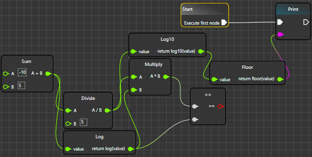
为了展示变量列表的功能,我们将尝试将这个公式  转化为图形表示。

在这里,我们可以轻松地观察到引入了两个特殊节点,Set 节点和 Get 节点。Set 节点充当一个子应用程序,将整个可视化操作的输出重定向到 X 变量。另一方面,Get 节点充当数据容器,它返回特定变量的值。
现在我们理解了变量列表如何通信及其目的,我们可以安全地深入研究它。
变量列表:添加/删除
添加变量意味着创建它并为其分配两个节点(Set、Get)。默认情况下,变量的类型是 Generic 且无名。
另一方面,删除变量并不那么容易。删除变量意味着删除与之相关的所有内容——例如,相关的 Get/Set 节点。
变量列表:利用
变量列表最有利的功能之一是它支持拖放机制。换句话说,您可以轻松地将变量拖放到您的图表中——然后,观看神奇的变化。

事实上,悬停元素,它代表了拖放机制的可视化,只不过是一个具有灵活属性的窗口。这些属性基于我们打算利用的变量的属性。
样式
    <Style x:Key="VariableHoster" TargetType="controls:VariableHoster">
        <Setter Property="ShowInTaskbar" Value="False" />
        <Setter Property="WindowStyle" Value="None" />
        <Setter Property="ResizeMode" Value="NoResize" />
        <Setter Property="Height" Value="25" />
        <Setter Property="Width" Value="100" />
        <Setter Property="Template">
            <Setter.Value>
                <ControlTemplate>
                    <Canvas Background="#353535">
                        <Border x:Name="GoldenBorder"
                                Width="{Binding RelativeSource=
                                {RelativeSource TemplatedParent},Path=ActualWidth}"
                                Height="{Binding RelativeSource=
                                {RelativeSource TemplatedParent},Path=ActualHeight}"
                                CornerRadius="4,4,4,4"
                                BorderThickness="2"
                                Background="{DynamicResource GlobalBackground}">
                            <Border.BorderBrush>
                                <RadialGradientBrush>
                                    <GradientStop Color="#FFFFB10C" Offset="0.215" />
                                    <GradientStop Color="#FF916E24" Offset="0" />
                                </RadialGradientBrush>
                            </Border.BorderBrush>
                        </Border>
                        <Border x:Name="Icon" Height="16"
                        Width="16" Margin="5,3,0,0">
                            <Border.Background>
                                <ImageBrush ImageSource="{Binding RelativeSource=
                                            {RelativeSource Self},Path=Icon}" />
                            </Border.Background>
                        </Border>
                        <TextBlock x:Name="VarName" Margin="25,3,0,0"
                                                    Foreground="AliceBlue" />
                    </Canvas>
                </ControlTemplate>
            </Setter.Value>
        </Setter>
    </Style>
变量列表:追踪
追踪你的变量意味着计算它被引用的次数。
例如,假设我们使用了变量 y 3 次(2 个 setter,1 个 getter),变量 x 也 3 次(1 个 setter,2 个 getter)。

我们应该看到这些注释显示为工具提示
 和
和 
通过将光标移到度数状图标上,将显示一个工具提示。该工具提示将告诉您此变量使用了多少次,以及使用类型是什么。
节点树

节点树是帮助您将节点添加到虚拟控件的工具。事实上,它是动态 TreeView 的组合。它的项目代表了我们拥有的每个节点的元数据。
在创建此控件的过程中,我偶然创建了 WPF TreeView 最快的过滤算法。因此,我和 Dirk 分享了我们的专业知识,并发布了一个更好、更优化的过滤算法。可以在这里找到:高级 WPF TreeViews in C#/VB.Net Part 3 of n。
节点树:模板

节点树有两种状态:预展开和后展开。
预展开
- 绿色:绿色区域代表可以最终用于过滤树的文本框。
- 红色:红色区域代表节点的类别,当然还有其中的节点。
后展开

- 蓝色:蓝色区域代表节点的标题。
- 绿色:绿色区域代表与节点相关的描述或工具提示。
或者,我们可以注意到树右侧的自定义滚动条。
节点树:分类和排序

所有节点都包含在一个DLL 文件中(作为一种灵活性,允许你创建插件/附加组件),每个节点都属于一个特定的类别。考虑到这一点,节点在树中的分类将基于现有的类别,即(Math、Arrays、Vectors 等)。
另一方面,类别的排序则基于其中包含的节点数量。
节点的类别是在创建过程中设置的。在其初始形式中,节点树将仅包含节点的类别——最终,它将遍历所有可用的节点并将它们分别放置。默认设置的唯一类别是variables类别,所有变量都将在此处托管。
构建类别的魔力
        private void BuildCategories()
        {
            _categories = new List<Dictionary<int, string>>();

            foreach (var node in _pluginsManager.LoadedNodes)
                if (!_catNames.Contains(node.Category))
                    _catNames.Add(node.Category);
            if (VariablesTreeRootIndex() != -1)
                _catNames.Remove("Variables");
            for (var index = 0; index < _catNames.Count; index++)
            {
                var name = _catNames[index];
                var dic = new Dictionary<int, string> {{index, name}};
                _categories.Add(dic);
            }
            for (var index = 0; index < _categories.Count; index++)
            {
                var item = _categories[index];
                var name = item[index];
                if (name != null) Roots.Add(new NodeItem("", name));
            }
        }
构建节点实例的魔力
        private void BuildNodes()
        {
            Task.Factory.StartNew(() =>
            {
                Dispatcher.BeginInvoke(new Action(() =>
                {
                    foreach (var node in _pluginsManager.LoadedNodes)
                        for (var index = 0; index < Roots.Count; index++)
                            if (node.Category == Roots[index].NodeName)
                                Roots[index].Nodes.Add(new NodeItem("", node.Clone()));
                }));
            });
        }
节点树:插入
通过插入,我们指的是创建一个特定节点的实例,并将其插入虚拟控件。也就是说,插入过程有两种不同的状态
- 通用插入:当你正常打开节点树时发生
- 修改插入:当你通过拖动节点的连线来打开节点树时发生
通用插入
你可以通过双击或使用虚拟控件的上下文菜单来打开节点树。最终,你选择你打算添加的节点,并通过按 [ENTER] 键或通过鼠标双击来简单地添加它。

修改插入
这一部分相对新颖。你不需要先添加一个节点,然后再链接它的端口到其他节点——你只需拖动你打算链接的连线,然后等待节点树显示所有可用选项。
链接操作将自动执行。

神奇的是,两种插入方法实际上有相同的后台代码。
        private void InsertNode(Node node)
        {
            Task.Factory.StartNew(() =>
            {
                Application.Current.Dispatcher.BeginInvoke
                            (DispatcherPriority.Render, new Action(() =>
                {
                    _host.AddNode(node, Canvas.GetLeft(this), Canvas.GetTop(this));

                    node.Dispatcher.BeginInvoke
                         (DispatcherPriority.Loaded, new Action(() =>
                    {
                        if (_host.TemExecPort != null && node.InExecPorts.Count > 0)
                            if (_host.TemExecPort.ConnectedConnectors.Count > 0)
                            {
                                string id1 = Guid.NewGuid().ToString(),
                                       id2 = Guid.NewGuid().ToString();

                                var thirdNode =
                                _host.TemExecPort.ConnectedConnectors[0].
                                EndPort.ParentNode;
                                NodesManager.CreateExecutionConnector
                                (_host, _host.TemExecPort, node.InExecPorts[0],
                                    id1);
                                NodesManager.CreateExecutionConnector
                                             (_host, node.OutExecPorts[0],
                                    thirdNode.InExecPorts[0], id2);
                            }
                            else
                            {
                                NodesManager.CreateExecutionConnector
                                (_host, _host.TemExecPort, node.InExecPorts[0]);
                            }
                        else if (_host.TemObjectPort != null &&
                                  node.InputPorts.Count > 0)
                            NodesManager.CreateObjectConnector
                                 (_host, _host.TemObjectPort, node.InputPorts[0]);
                    }));
                }));
            });
        }
调用上述函数和创建节点
                    var hostedNode = ((NodeItem) _tv.SelectedItem)?.HostedNode;
                    if (hostedNode != null)
                    {
                        var node = hostedNode.Clone();
                        InsertNode(node);
                        Remove();
                    }
节点树的能力不仅限于此,它还可以管理变量。

我们在截图中的变量X 和Y。
内部消息框
此控件用作内部通知、工具提示和指示器。它有一个作为标志的图标。我们在讨论链接可能性时已经讨论过这个组件的作用。
        public enum InnerMessageIcon
        {
            Correct,
            Warning,
            False
        }
搜索窗口

每个节点都有一个内置函数,如果它包含我们正在寻找的项目的元数据,则返回一个 TreeViewItem。如果不包含,则返回null。
           public virtual FoundItem Search(string key)
        {
            if (IsCollapsed) return null;
            var KEY = key.ToUpper();
            var fi = new FoundItem();
            if (Title.ToUpper().Contains(KEY))
            {
                fi.foundNode = this;
                fi.Hint = Title;
                fi.Type = ItemTypes.Node;
            }
            foreach (var port in InputPorts)
                if (port.IsVisible)
                {
                    if (port.Control is TextBox)
                    {
                        if (((TextBox) port.Control).Text.ToUpper().Contains(KEY))
                        {
                            if (fi.Hint != Title)
                                fi.Hint = Title;
                            fi.Items.Add(new FoundItem
                            {
                                Hint = $"   In input :{(port.Control as TextBox).Text}",
                                Type = ItemTypes.Port,
                                foundNode = this
                            });
                        }
                    }
                    else
                    {
                        var textBox = port.Control as UnrealControlsCollection.TextBox;
                        if (textBox == null ||
                            !textBox.Text.ToUpper().Contains(KEY)) continue;
                        var box = port.Control as UnrealControlsCollection.TextBox;
                        if (box != null)
                            if (fi.Hint != Title)
                                fi.Hint = Title;
                        fi.Items.Add(new FoundItem(port.Background)
                        {
                            Hint = $"In input :{box.Text}",
                            Type = ItemTypes.Port,
                            foundNode = this,
                            Brush = port.StrokeBrush
                        });
                    }
                }
                else
                {
                    var textBox = port.Control as UnrealControlsCollection.TextBox;
                    if (textBox == null ||
                       !textBox.Text.ToUpper().Contains(KEY)) continue;
                    var box = port.Control as UnrealControlsCollection.TextBox;
                    if (box != null)
                        if (fi.Hint != Title)
                            fi.Hint = Title;
                    fi.Items.Add(new FoundItem(port.Background)
                    {
                        Hint = $"In input :{box.Text}",
                        Type = ItemTypes.Port,
                        foundNode = this,
                        Brush = port.StrokeBrush
                    });
                }
            foreach (var port in OutputPorts)
                if (port.IsVisible)
                {
                    if (port.Control is TextBox)
                    {
                        if (((TextBox) port.Control).Text.ToUpper().Contains(KEY))
                        {
                            if (fi.Hint != Title)
                                fi.Hint = Title;
                            fi.Items.Add(new FoundItem
                            {
                                Hint = $"   In input :{(port.Control as TextBox).Text}",
                                Type = ItemTypes.Port,
                                foundNode = this
                            });
                        }
                    }
                    else
                    {
                        var textBox = port.Control as UnrealControlsCollection.TextBox;
                        if (textBox == null ||
                           !textBox.Text.ToUpper().Contains(KEY)) continue;
                        var box = port.Control as UnrealControlsCollection.TextBox;
                        if (box != null)
                            if (fi.Hint != Title)
                                fi.Hint = Title;
                        fi.Items.Add(new FoundItem(port.Background)
                        {
                            Hint = $"In input :{box.Text}",
                            Type = ItemTypes.Port,
                            foundNode = this,
                            Brush = port.StrokeBrush
                        });
                    }
                }
                else
                {
                    var textBox = port.Control as UnrealControlsCollection.TextBox;
                    if (textBox == null ||
                       !textBox.Text.ToUpper().Contains(KEY)) continue;
                    var box = port.Control as UnrealControlsCollection.TextBox;
                    if (box != null)
                        if (fi.Hint != Title)
                            fi.Hint = Title;
                    fi.Items.Add(new FoundItem(port.Background)
                    {
                        Hint = $"In input :{box.Text}",
                        Type = ItemTypes.Port,
                        foundNode = this,
                        Brush = port.StrokeBrush
                    });
                }
            if (fi.Hint != Title)
                return null;
            fi.foundNode = this;
            return fi;
        }
一旦我们启动搜索操作,算法将迭代所有节点并检查它们是否包含类似的元数据。如果是,那么将返回的 TreeViewItem 将托管在搜索窗口中。
FoundItem 将作为独立的组件本身运行。通过双击它,它将带您找到包含数据的节点。
     public class FoundItem : TreeViewItem
    {
        private readonly Path ctrl =
        new Path {Width = 15, Height = 15, Margin = new Thickness(0, -2, 0, 0)};

        private readonly TextBlock hint =
            new TextBlock {Foreground = Brushes.WhiteSmoke,
                           Background = Brushes.Transparent};

        private string _hint;

        private Brush brush;

        public ItemTypes Type;

        public FoundItem(Brush b = null)
        {
            IsExpanded = true;
            Loaded += (s, e) =>
            {
                MouseDoubleClick += FoundItem_MouseDoubleClick;

                var sp = new StackPanel {Orientation = Orientation.Horizontal,
                                         MaxHeight = 20};
                sp.Children.Add(ctrl);
                sp.Children.Add(hint);
                Header = sp;
                if (Type == ItemTypes.Port)
                {
                    ctrl.Style = FindResource("ObjectPin") as Style;
                    ctrl.Stroke = b;
                }
                else
                {
                    ctrl.Style = FindResource("ExecPin") as Style;
                }
            };
        }

        public string Hint
        {
            get { return _hint; }
            set
            {
                _hint = value;
                if (hint != null) hint.Text = value;
            }
        }

        public Brush Brush
        {
            get { return brush; }
            set
            {
                brush = value;
                ctrl.Stroke = value;
                ctrl.Fill = value;
            }
        }

        public Node foundNode { get; set; }

        private void FoundItem_MouseDoubleClick(object sender, MouseButtonEventArgs e)
        {
            foundNode.Host.GoForNode(foundNode);
        }
    }
GoForNode 是一个以节点作为参数的函数。它移动 VirtualControl 上渲染的所有 UIElement,以便将选定的节点置于屏幕中心。
         public void GoForNode(Node node)
        {
            node.X = Math.Truncate(node.X);
            node.Y = Math.Truncate(node.Y);
            var origin = BasisOrigin;
            origin.X -= node.ActualWidth - 10;
            origin.X = Math.Truncate(origin.X);
            origin.Y = Math.Truncate(origin.Y);
            var difference = Point.Subtract(origin, new Point(node.X, node.Y));
            var timer = new DispatcherTimer {Interval = new TimeSpan(0, 0, 0, 0, 01)};
            foreach (var n in Nodes)
            {
                if (difference.X < 0)
                    n.X += difference.X;
                else
                    n.X += difference.X;
                if (difference.Y < 0)
                    n.Y += difference.Y;
                else
                    n.Y += difference.Y;
                NeedsRefresh = true;
            }
            difference.X = 10;
            difference.Y = 0;
            if (difference.X != 0 || difference.Y != 0)
                timer.Start();
            timer.Tick += (s, e) =>
            {
                if (difference.X == 0 && difference.Y == 0)
                    timer.Stop();
                foreach (var n in Nodes)
                {
                    if (difference.X > 0)
                        n.X++;
                    else
                        n.X--;
                    if (difference.Y > 0)
                        n.Y++;
                    else
                        n.Y--;
                }
                if (difference.X > 0)
                    difference.X--;
                else
                    difference.X++;
                if (difference.Y > 0)
                    difference.Y--;
                else
                    difference.Y++;
            };
            SelectedNodes.Clear();
            SelectedNodes.Add(node);
        }

内容浏览器
内容浏览器扮演着一个文件浏览器的角色,该浏览器可以适应可视化脚本环境。

概述
内容浏览器虽然尚未稳定,但它是一个可以作为可视化脚本环境和硬盘文件之间桥梁的工具。它的作用与 Visual Studio 的解决方案资源管理器相同,但更具原创性。
模板
模板非常通用,分为三个部分。
- 工具栏
工具栏是一个面板,包含几个按钮,允许您创建新文件/文件夹、导入现有文件以及保存您所做的所有更改。此外,它还支持撤销/重做操作。
- 文件夹浏览器
文件夹浏览器是一个树,代表指定路径中的所有文件夹。
-
内容浏览器
每个文件和文件夹都会显示在内容浏览器中。不仅如此,它还会根据文件扩展名对文件进行分类,为它们提供特定的颜色,以帮助我们区分差异。

即

另一方面,文件夹也更灵活。事实上,文件夹是两个路径的组合(又名,2D 形状)。您可以轻松自定义文件夹,通过更改其颜色和形状。
-
文件夹头部

如前所述,文件夹分为两个组件。文件夹的头部和核心。
-
文件夹核心

文件夹的核心是路径的一部分,其颜色会最终改变。
轻松更改文件夹颜色。以下是两个示例


-
-
搜索栏
这里没有什么花哨或复杂的。它是一个栏,可以根据 Windows 的标准搜索模式过滤你正在浏览的文件。
示例:“*.txt* 显示仅扩展名为 '.txt' 的文件。
样式
ExplorerItem
<Style x:Key="ContentBrowserElement" TargetType="{x:Type ListViewItem}">
<Setter Property="HorizontalAlignment" Value="Left" />
<Setter Property="FocusVisualStyle" Value="{x:Null}" />
<Setter Property="Template">
<Setter.Value>
<ControlTemplate TargetType="{x:Type ListViewItem}">
<Grid HorizontalAlignment="Left" VerticalAlignment="Top">
<Border x:Name="border"
BorderBrush="{x:Null}" BorderThickness="1"
HorizontalAlignment="Stretch"
VerticalAlignment="Stretch" CornerRadius="2.5" />
<WrapPanel HorizontalAlignment="Stretch"
VerticalAlignment="Stretch">
<ContentPresenter Margin="3,3,5,30" />
</WrapPanel>
</Grid>
</ControlTemplate>
</Setter.Value>
</Setter>
</Style>
<Style x:Key="ExplorerItem" TargetType="controls:ExplorerItem">
<Setter Property="Template">
<Setter.Value>
<ControlTemplate>
<Border x:Name="ExplorerItemContainer" CornerRadius="8">
<StackPanel Orientation="Vertical" Margin="3"
Background="{Binding BackColor}" Width="68"
Height="100"
ClipToBounds="True">
<Canvas x:Name="Image" Visibility="Hidden">
<Rectangle Fill="{Binding ItemColor}"
Opacity=".4" Canvas.Left="2"
x:Name="SelectionBox"
Height="64" Width="64"
StrokeThickness="1">
<Rectangle.Effect>
<BlurEffect Radius="3" />
</Rectangle.Effect>
</Rectangle>
<Rectangle Canvas.Left="2" Canvas.Top="57"
Height="6.4" Width="64"
Fill="{Binding ItemColor}"
RadiusY="4" RadiusX="4" />
<Rectangle x:Name="Thumbnail" Width="42"
Height="42" Canvas.Left="12"
Canvas.Top="6" />
</Canvas>
<Grid x:Name="Folder"
ClipToBounds="True" Margin="0,12,0,0"
Visibility="Hidden" Width="52" Height="52">
<StackPanel Orientation="Vertical">
<Path Stretch="Uniform"
StrokeThickness="1.33333337">
<Path.Fill>
<LinearGradientBrush>
<GradientStop Color="#FF141F2B"
Offset="0.774" />
<GradientStop Color="#FF979797" />
</LinearGradientBrush>
</Path.Fill>
<Path.Data>
<PathGeometry
Figures="m 36.08425 225.37304
c 3.687503 -0.38572 5.000001
-1.13954 5.000001 -2.87168 0
-4.92432 4.279726 -14.59278
8.064553 -18.21887 2.169627
-2.07864 6.743628 -5.31508
10.164449 -7.19208 9.241516
-5.07084 10.814177 -8.05027
12.940261 -24.5155 1.607543
-12.44945 2.399082 -15.09711
5.751785 -19.23949 2.138244
-2.64187 6.255744 -6.04563 9.150001
-7.56391 5.140936 -2.69685 7.276218
-2.77019 92.59562 -3.18018 95.45312
-0.45869 98.15761 -0.28718 106.152
6.73198 7.0916 6.22651 8.7382 10.6307
9.68435 25.90307 0.73396 11.84719
1.26586 14.14613 3.87724 16.75775
l 3.02658 3.02687 163.62993 0.66666
c 162.75799 0.66312 163.65832 0.68152
168.96324 3.45406 6.35662 3.3222
12.57175 12.61305 13.60857 20.3431
0.69946 5.21488 0.91185 5.41624
6.22446 5.90136 3.02518 0.27624
-136.0997 0.50623 -309.16637
0.51107 -173.06667 0.005
-312.41667 -0.22655 -309.66667
-0.51421 z"
FillRule="NonZero" />
</Path.Data>
</Path>
<Path Margin="0,-2,0,0" Stretch="Uniform"
StrokeThickness="1.33333337">
<Path.Fill>
<LinearGradientBrush EndPoint="0.5,1"
StartPoint="0.5,0">
<GradientStop Color="Black"
Offset="1.5" />
<GradientStop Color="#FF6E6E6E"
Offset="0.029" />
<GradientStop Color="#FF000102" />
</LinearGradientBrush>
</Path.Fill>
<Path.Data>
<PathGeometry
Figures="m 35.46142 662.88211
c -5.645595 -6.04364 -6.953389
-12.93947 -7.582867 -39.98349
-0.31759 -13.64451 -1.179782
-51.50821 -1.915981 -84.14154
-1.96164 -86.95319 -5.166926
-162.45026 -9.992734 -235.36814
-1.271839 -19.21746 -1.512834
-30.87022 -0.697253 -33.71399
2.083099 -7.26333 6.312426
-12.8508 12.339504 -16.302
l 5.732545 -3.28255 314.483266
-0.34436 c 218.55465 -0.2393
316.08585 0.0872 319.73701
1.07034 6.94134 1.8691
15.21772 10.23518 17.12215
17.30772 1.12319 4.17118
0.98421 13.3284 -0.57271
37.73698 -5.17222 81.08726
-8.05125 149.04533 -10.06429
237.56267 -2.32833 102.38191
-2.43281 105.12652 -4.2054
110.47999 -0.93725 2.83066
-3.32391 6.88066 -5.30367
9 l -3.59956 3.85334 H
350.01131 39.081194 Z"
FillRule="NonZero" />
</Path.Data>
<Path.Effect>
<DropShadowEffect BlurRadius="5"
Color="Black" />
</Path.Effect>
</Path>
</StackPanel>
</Grid>
<Label x:Name="Tag" BorderBrush="Transparent"
VerticalAlignment="Center"
Background="Transparent" HorizontalAlignment="Center">
<TextBlock Foreground="{Binding Foreground}"
VerticalAlignment="Center" MaxWidth="65"
MaxHeight="40" TextWrapping="Wrap"
Background="Transparent"
TextTrimming="CharacterEllipsis"
HorizontalAlignment="Center"
Text="{Binding ItemName}" />
</Label>
<TextBox Visibility="Collapsed" x:Name="RenameBox"
Text="{Binding ItemName}"
Background="Transparent" Foreground="WhiteSmoke"
TextWrapping="Wrap" AcceptsReturn="True"
VerticalScrollBarVisibility="Disabled"
HorizontalAlignment="Center" MaxWidth="64"
MaxHeight="40"
BorderBrush="White" BorderThickness="1">
<TextBox.Effect>
<DropShadowEffect BlurRadius="10" Color="White" />
</TextBox.Effect>
</TextBox>
</StackPanel>
<Border.ContextMenu>
<ContextMenu />
</Border.ContextMenu>
</Border>
<ControlTemplate.Triggers>
<Trigger Property="IsMouseOver" Value="True">
<Setter TargetName="ExplorerItemContainer"
Property="Background">
<Setter.Value>
<DrawingBrush>
<DrawingBrush.Drawing>
<DrawingGroup>
<GeometryDrawing>
<GeometryDrawing.Brush>
<LinearGradientBrush
StartPoint="0,0" EndPoint="0,1"
SpreadMethod="Pad">
<GradientStop
Color="#FF6C6C6C" Offset="1" />
<GradientStop
Color="#22FFFFFF" Offset="0" />
</LinearGradientBrush>
</GeometryDrawing.Brush>
<GeometryDrawing.Geometry>
<RectangleGeometry
Rect="0,0 1,0.48" />
</GeometryDrawing.Geometry>
</GeometryDrawing>
</DrawingGroup>
</DrawingBrush.Drawing>
</DrawingBrush>
</Setter.Value>
</Setter>
</Trigger>
<DataTrigger Binding="{Binding IsSelected}" Value="True">
<Setter TargetName="ExplorerItemContainer"
Property="Border.Background">
<Setter.Value>
<LinearGradientBrush StartPoint="0,0" EndPoint="0,1"
SpreadMethod="Pad">
<GradientStop Color="#99FFE909" Offset="1" />
<GradientStop Color="#FF232000" Offset="0" />
</LinearGradientBrush>
</Setter.Value>
</Setter>
<Setter TargetName="ExplorerItemContainer"
Property="Border.BorderThickness" Value="2" />
<Setter TargetName="ExplorerItemContainer"
Property="Border.BorderBrush">
<Setter.Value>
<LinearGradientBrush StartPoint="0,0" EndPoint="0,1"
SpreadMethod="Pad">
<GradientStop Color="#99FFB109" Offset="0" />
<GradientStop Color="#CC383302" Offset="1" />
</LinearGradientBrush>
</Setter.Value>
</Setter>
</DataTrigger>
</ControlTemplate.Triggers>
</ControlTemplate>
</Setter.Value>
</Setter>
<Setter Property="ToolTip">
<Setter.Value>
<Grid>
<Border CornerRadius="5">
<Border.Background>
<LinearGradientBrush>
<GradientStop Color="#99CD3800" Offset="0.763" />
<GradientStop Color="#FFCB8C1F" Offset="0.028" />
</LinearGradientBrush>
</Border.Background>
<StackPanel Orientation="Vertical" Background="#353535"
Margin="3,3,3,3">
<StackPanel Orientation="Horizontal">
<TextBlock Text="File Name: "
Foreground="Gray" FontSize="13" />
<TextBlock Foreground="WhiteSmoke"
Text="{Binding ItemName}" FontSize="13" />
</StackPanel>
<Border BorderBrush="Azure" BorderThickness="0,1,0,0"
Margin="0,8" Background="#FF09172B" />
<StackPanel Orientation="Horizontal">
<TextBlock Text="Type: " Foreground="Gray" />
<TextBlock Foreground="WhiteSmoke"
Text="{Binding Extension}" />
</StackPanel>
<StackPanel Orientation="Horizontal">
<TextBlock Text="Size: " Foreground="Gray" />
<TextBlock Foreground="WhiteSmoke"
Text="{Binding Size}" />
</StackPanel>
<StackPanel Orientation="Horizontal">
<TextBlock Text="Path: " Foreground="Gray" />
<TextBlock Foreground="WhiteSmoke"
Text="{Binding Path}" MaxWidth="300"
Margin="0,0,3,0" TextWrapping="Wrap" />
</StackPanel>
</StackPanel>
</Border>
</Grid>
</Setter.Value>
</Setter>
</Style>
<Style TargetType="ToolTip">
<Setter Property="Template">
<Setter.Value>
<ControlTemplate TargetType="ToolTip">
<ContentPresenter />
</ControlTemplate>
</Setter.Value>
</Setter>
</Style>
文件夹(头部)
     <Path Stretch="Uniform" StrokeThickness="1.33333337">
                                        <Path.Fill>
                                            <LinearGradientBrush>
                                                <GradientStop Color="#FF141F2B"
                                                              Offset="0.774" />
                                                <GradientStop Color="#FF979797" />
                                            </LinearGradientBrush>
                                        </Path.Fill>
                                        <Path.Data>
                                            <PathGeometry
                                                Figures="m 36.08425 225.37304 c
                                                3.687503 -0.38572 5.000001 -1.13954
                                                5.000001 -2.87168 0 -4.92432 4.279726
                                                -14.59278 8.064553 -18.21887 2.169627
                                                -2.07864 6.743628 -5.31508 10.164449
                                                -7.19208 9.241516 -5.07084 10.814177
                                                -8.05027 12.940261 -24.5155 1.607543
                                                -12.44945 2.399082 -15.09711 5.751785
                                                -19.23949 2.138244 -2.64187 6.255744
                                                -6.04563 9.150001 -7.56391 5.140936
                                                -2.69685 7.276218 -2.77019 92.59562
                                                -3.18018 95.45312 -0.45869 98.15761
                                                -0.28718 106.152 6.73198 7.0916
                                                6.22651 8.7382 10.6307 9.68435
                                                25.90307 0.73396 11.84719 1.26586
                                                14.14613 3.87724 16.75775 l 3.02658
                                                3.02687 163.62993 0.66666 c 162.75799
                                                0.66312 163.65832 0.68152 168.96324
                                                3.45406 6.35662 3.3222 12.57175
                                                12.61305 13.60857 20.3431 0.69946
                                                5.21488 0.91185 5.41624 6.22446
                                                5.90136 3.02518 0.27624 -136.0997
                                                0.50623 -309.16637 0.51107 -173.06667
                                                0.005 -312.41667 -0.22655 -309.66667
                                                -0.51421 z"
                                                FillRule="NonZero" />
                                        </Path.Data>
    </Path>
文件夹(核心)
     <Path Margin="0,-2,0,0" Stretch="Uniform"
     StrokeThickness="1.33333337">
                                        <Path.Fill>
                                            <LinearGradientBrush EndPoint="0.5,1"
                                                 StartPoint="0.5,0">
                                                <GradientStop Color="Black"
                                                              Offset="1.5" />
                                                <GradientStop Color="#FF6E6E6E"
                                                              Offset="0.029" />
                                                <GradientStop Color="#FF000102" />
                                            </LinearGradientBrush>
                                        </Path.Fill>
                                        <Path.Data>
                                            <PathGeometry
                                                Figures="m 35.46142 662.88211
                                                c -5.645595 -6.04364 -6.953389
                                                -12.93947 -7.582867 -39.98349
                                                -0.31759 -13.64451 -1.179782 -51.50821
                                                -1.915981 -84.14154 -1.96164 -86.95319
                                                -5.166926 -162.45026 -9.992734 -235.36814
                                                -1.271839 -19.21746 -1.512834 -30.87022
                                                -0.697253 -33.71399 2.083099 -7.26333
                                                6.312426 -12.8508 12.339504 -16.302 l
                                                5.732545 -3.28255 314.483266 -0.34436
                                                c 218.55465 -0.2393 316.08585 0.0872
                                                319.73701 1.07034 6.94134 1.8691
                                                15.21772 10.23518 17.12215 17.30772
                                                1.12319 4.17118 0.98421 13.3284
                                                -0.57271 37.73698 -5.17222 81.08726
                                                -8.05125 149.04533 -10.06429 237.56267
                                                -2.32833 102.38191 -2.43281 105.12652
                                                -4.2054 110.47999 -0.93725 2.83066
                                                -3.32391 6.88066 -5.30367 9 l
                                                -3.59956 3.85334 H 350.01131
                                                39.081194 Z"
                                                FillRule="NonZero" />
                                        </Path.Data>
                                        <Path.Effect>
                                            <DropShadowEffect BlurRadius="5"
                                                              Color="Black" />
                                        </Path.Effect>
    </Path>
实现
这个文件浏览器是为了完全集成到系统中而创建的。它允许你浏览数据科学家可以使用的文件。不仅如此,你还可以根据这些文件生成节点。


性能指示器

性能指示器是我出于好玩而制作的工具。然而,将其添加到项目中已被证明很有用。它帮助我跟踪可视化脚本环境使用了多少资源。
样式
<Style x:Key="Gauge" TargetType="controls:PerformanceGauge">
<Setter Property="Template">
<Setter.Value>
<ControlTemplate>
<Grid Width="270" Height="30">
<Path Style="{DynamicResource ToolTipHint}"
HorizontalAlignment="Left" Name="Spy"
Stretch="Uniform" StrokeThickness="1.33333325">
<Path.ToolTip>
<Border Background="#424242"
BorderBrush="Gray" CornerRadius="3,3,3,3"
BorderThickness="2">
<StackPanel MaxWidth="300" Margin="3">
<TextBlock Foreground="Gold" FontSize="14"
Text="Performance gauge"
FontFamily="Segoe UI Semibold" />
<TextBlock Foreground="AliceBlue"
Text="This gauge will help you
maintain the performaance of your
running project."
TextWrapping="Wrap" />
</StackPanel>
</Border>
</Path.ToolTip>
</Path>
<Grid Height="30" Width="180">
<Path xmlns:x="http://schemas.microsoft.com/winfx/2006/xaml"
Name="Gauge"
StrokeThickness="3" StrokeLineJoin="Miter"
StrokeStartLineCap="Flat"
StrokeEndLineCap="Flat" Stretch="Fill"
Fill="#FF353535">
<Path.Stroke>
<LinearGradientBrush EndPoint="0.5,1"
StartPoint="0.5,0">
<GradientStop Color="#FF202934"
Offset="0.623" />
<GradientStop
Color="{Binding RelativeSource=
{RelativeSource TemplatedParent},
Path=CoreColor}" />
</LinearGradientBrush>
</Path.Stroke>
<Path.Data>
<PathGeometry
Figures="m 10 2.519685 h 240 v 30 h 40 v
-30 H 790 L 660 152.51969 H 290 v -30 h
-40 v 30 H 10 Z"
FillRule="NonZero" />
</Path.Data>
</Path>
<TextBlock Text="{Binding RelativeSource=
{RelativeSource TemplatedParent},Path=Ram}"
Foreground="WhiteSmoke" Margin="8"
FontFamily="Segoe WP Semibold" />
<StackPanel Orientation="Horizontal"
RenderTransformOrigin="0.444,0.5" Height="30"
VerticalAlignment="Top"
HorizontalAlignment="Left"
Width="180" Margin="70,1,0,0">
<Path xmlns:x=
"http://schemas.microsoft.com/winfx/2006/xaml"
x:Name="Cold" Fill="Black"
Height="15" Stretch="Fill"
Width="15" HorizontalAlignment="Left"
Stroke="#FFBFBFBF">
<Path.Data>
<PathGeometry
Figures="M 64.00 416.00l 96.00
96.00l 256.00-256.00L 160.00 0.00L
64.00 96.00l 160.00 160.00L 64.00 416.00z"
FillRule="NonZero" />
</Path.Data>
<Path.ToolTip>
<Border Background="#424242"
BorderBrush="Gray"
CornerRadius="3,3,3,3"
BorderThickness="2">
<StackPanel MaxWidth="300"
Margin="3">
<TextBlock Foreground="#FF00A2FF"
FontSize="14" Text="Cold state"
FontFamily="Segoe UI Semibold" />
<TextBlock Foreground="AliceBlue"
Text="This level of performance
indicates that your project
is running in the best possible state."
TextWrapping="Wrap" />
<TextBlock Foreground="Green"
Text="You don't need
to take any actions." />
</StackPanel>
</Border>
</Path.ToolTip>
</Path>
<Path xmlns:x=
"http://schemas.microsoft.com/winfx/2006/xaml"
x:Name="Cool"
Fill="#FF000000" Height="15"
Stretch="Fill" Width="15"
Margin="-4,0,0,0"
HorizontalAlignment="Left"
Stroke="#FFBFBFBF">
<Path.Data>
<PathGeometry
Figures="M 64.00 416.00l 96.00
96.00l 256.00-256.00L 160.00 0.00L
64.00 96.00l 160.00 160.00L 64.00 416.00z"
FillRule="NonZero" />
</Path.Data>
<Path.ToolTip>
<Border Background="#424242"
BorderBrush="Gray" CornerRadius="3,3,3,3"
BorderThickness="2">
<StackPanel MaxWidth="300"
Margin="3">
<TextBlock Foreground="#FF0074FF"
FontSize="14" Text="Cool state"
FontFamily="Segoe UI Semibold" />
<TextBlock Foreground="AliceBlue"
Text="This level of performance
indicates that your project is running
in the near-best possible state."
TextWrapping="Wrap" />
<TextBlock Foreground="Green"
Text="You don't need to
take any actions." />
</StackPanel>
</Border>
</Path.ToolTip>
</Path>
<Path xmlns:x=
"http://schemas.microsoft.com/winfx/2006/xaml"
x:Name="Good"
Fill="#FF000000" Height="15"
Stretch="Fill" Width="15"
Margin="-4,0,0,0"
HorizontalAlignment="Left"
Stroke="#FFBFBFBF">
<Path.Data>
<PathGeometry
Figures="M 64.00 416.00l 96.00
96.00l 256.00-256.00L 160.00 0.00L
64.00 96.00l 160.00 160.00L 64.00 416.00z"
FillRule="NonZero" />
</Path.Data>
<Path.ToolTip>
<Border Background="#424242"
BorderBrush="Gray" CornerRadius="3,3,3,3"
BorderThickness="2">
<StackPanel MaxWidth="300"
Margin="3">
<TextBlock Foreground="#FF0074FF"
FontSize="14" Text="Good state"
FontFamily="Segoe UI Semibold" />
<TextBlock Foreground="AliceBlue"
Text="This level of performance
indicates that your project is running
in the near-best possible state."
TextWrapping="Wrap" />
<TextBlock Foreground="Green"
Text="You don't need
to take any actions." />
</StackPanel>
</Border>
</Path.ToolTip>
</Path>
<Path xmlns:x=
"http://schemas.microsoft.com/winfx/2006/xaml"
x:Name="Normal"
Fill="#FF000000" Height="15"
Stretch="Fill" Width="15"
Margin="-4,0,0,0"
HorizontalAlignment="Left"
Stroke="#FFBFBFBF">
<Path.Data>
<PathGeometry
Figures="M 64.00 416.00l 96.00
96.00l 256.00-256.00L 160.00 0.00L
64.00 96.00l 160.00 160.00L 64.00 416.00z"
FillRule="NonZero" />
</Path.Data>
<Path.ToolTip>
<Border Background="#424242"
BorderBrush="Gray" CornerRadius="3,3,3,3"
BorderThickness="2">
<StackPanel MaxWidth="300"
Margin="3">
<TextBlock Foreground="WhiteSmoke"
FontSize="14" Text="Normal state"
FontFamily="Segoe UI Semibold" />
<TextBlock Foreground="AliceBlue"
Text="This level of performance
indicates that your project is
running in the normal state."
TextWrapping="Wrap" />
<TextBlock Foreground="Green"
Text="You don't need
to take any actions." />
</StackPanel>
</Border>
</Path.ToolTip>
</Path>
<Path xmlns:x=
"http://schemas.microsoft.com/winfx/2006/xaml"
x:Name="Heating"
Fill="#FF000000" Height="15"
Stretch="Fill" Width="15"
Margin="-4,0,0,0"
HorizontalAlignment="Left"
Stroke="#FFBFBFBF">
<Path.Data>
<PathGeometry
Figures="M 64.00 416.00l 96.00
96.00l 256.00-256.00L 160.00 0.00L
64.00 96.00l 160.00 160.00L 64.00 416.00z"
FillRule="NonZero" />
</Path.Data>
<Path.ToolTip>
<Border Background="#424242"
BorderBrush="Gray" CornerRadius="3,3,3,3"
BorderThickness="2">
<StackPanel MaxWidth="300"
Margin="3">
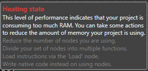
<TextBlock Foreground="#FFDC3E36"
FontSize="14" Text="Heating state"
FontFamily="Segoe UI Semibold" />
<TextBlock Foreground="AliceBlue"
Text="This level of performance
indicates that your project is consuming
too much RAM. You can take some actions
to reduce the amount of memory
your project is using."
TextWrapping="Wrap" />
<TextBlock Foreground="Gray"
Text="Reduce the number of nodes
you are using." />
<TextBlock Foreground="Gray"
Text="Divide your set of nodes
into multiple functions." />
<TextBlock Foreground="Gray"
Text="Load instructions
via the 'Load' node." />
<TextBlock Foreground="Gray"
Text="Write native code
instead on using nodes." />
</StackPanel>
</Border>
</Path.ToolTip>
</Path>
<Path x:Name="Hot"
Fill="#FF000000" Height="15"
Stretch="Fill" Width="15" Margin="-4,0,0,0"
HorizontalAlignment="Left" Stroke="#FFBFBFBF">
<Path.Data>
<PathGeometry
Figures="M 64.00 416.00l 96.00
96.00l 256.00-256.00L
160.00 0.00L 64.00 96.00l 160.00
160.00L 64.00 416.00z"
FillRule="NonZero" />
</Path.Data>
<Path.ToolTip>
<Border Background="#424242"
BorderBrush="Gray" CornerRadius="3,3,3,3"
BorderThickness="2">
<StackPanel MaxWidth="300" Margin="3">
<TextBlock Foreground="#FFDA0808"
FontSize="14" Text="Hot state"
FontFamily="Segoe UI Semibold" />
<TextBlock Foreground="AliceBlue"
Text="This level of performance
indicates that your project is consuming
too much RAM. You can take some actions
to reduce the amount of memory
your project is using."
TextWrapping="Wrap" />
<TextBlock Foreground="Gray"
Text="Reduce the number of nodes
you are using." />
<TextBlock Foreground="Gray"
Text="Divide your set of nodes
into multiple functions." />
<TextBlock Foreground="Gray"
Text="Load instructions
via the 'Load' node." />
<TextBlock Foreground="Gray"
Text="Write native code
instead on using nodes." />
</StackPanel>
</Border>
</Path.ToolTip>
</Path>
<Path xmlns:x=
"http://schemas.microsoft.com/winfx/2006/xaml"
x:Name="Risky"
Fill="#FF000000" Height="15"
Stretch="Fill" Width="15"
Margin="-4,0,0,0"
HorizontalAlignment="Left" Stroke="#FFBFBFBF">
<Path.Data>
<PathGeometry
Figures="M 64.00 416.00l 96.00
96.00l 256.00-256.00L 160.00 0.00L
64.00 96.00l 160.00 160.00L 64.00 416.00z"
FillRule="NonZero" />
</Path.Data>
<Path.ToolTip>
<Border Background="#424242"
BorderBrush="Gray" CornerRadius="3,3,3,3"
BorderThickness="2">
<StackPanel MaxWidth="300"
Margin="3">
<TextBlock Foreground="#FFF50909"
FontSize="14" Text="Risky state"
FontFamily="Segoe UI Semibold" />
<TextBlock Foreground="AliceBlue"
Text="This level of performance
indicates that your project is consuming
too much RAM. You can take some actions
to reduce the amount of memory
your project is using."
TextWrapping="Wrap" />
<TextBlock Foreground="Gray"
Text="Reduce the number of nodes
you are using." />
<TextBlock Foreground="Gray"
Text="Divide your set of nodes
into multiple functions." />
<TextBlock Foreground="Gray"
Text="Load instructions via the
'Load' node." />
<TextBlock Foreground="Gray"
Text="Write native code
instead on using nodes." />
</StackPanel>
</Border>
</Path.ToolTip>
</Path>
</StackPanel>
</Grid>
</Grid>
</ControlTemplate>
</Setter.Value>
</Setter>
</Style>
该指示器在内存使用方面有七种可能的状态。
- 冷

- 凉爽

- Good

- 正常

- 加热中
- 热

- 危险

请注意,当你使用更多内存资源时出现的建议实际上并不适用。
后台代码
using System;
using System.ComponentModel;
using System.Diagnostics;
using System.Threading.Tasks;
using System.Windows;
using System.Windows.Controls;
using System.Windows.Media;
using System.Windows.Shapes;
using System.Windows.Threading;
using VisualSR.Properties;

namespace VisualSR.Controls
{
    public enum PerfomanceState
    {
        Cold,
        Cool,
        Good,
        Normal,
        Heating,
        Hot,
        Risky
    }

    public class PerformanceGauge : Control, INotifyPropertyChanged
    {
        private readonly DispatcherTimer _backgroundRamCollector = new DispatcherTimer();

        private readonly PerformanceCounter _pc = new PerformanceCounter
        {
            CategoryName = "Process",
            CounterName = "Working Set - Private"
        };

        private readonly Process _proc = Process.GetCurrentProcess();
        private Path _cold;
        private Path _cool;
        private Color _coreColor;
        private Path _good;
        private Brush _heatColor;
        private Path _heating;
        private Path _hot;
        private double _memsize;
        private Path _normal;

        private Path[] _paths;
        private string _ram = "...";
        private Path _risky;
        public PerfomanceState States = PerfomanceState.Cold;

        public PerformanceGauge()
        {
            Style = FindResource("Gauge") as Style;
            ApplyTemplate();
            Loaded += (s, e) =>
            {
                _cold = Template.FindName("Cold", this) as Path;
                _cool = Template.FindName("Cool", this) as Path;
                _good = Template.FindName("Good", this) as Path;
                _normal = Template.FindName("Normal", this) as Path;
                _heating = Template.FindName("Heating", this) as Path;
                _hot = Template.FindName("Hot", this) as Path;
                _risky = Template.FindName("Risky", this) as Path;
                _paths = new[] {_cold, _cool, _good, _normal, _heating, _hot, _risky};
            };
            _backgroundRamCollector.Interval = new TimeSpan(0, 0, 0, 3);
            _backgroundRamCollector.IsEnabled = true;
            _backgroundRamCollector.Start();
            _backgroundRamCollector.Tick += (ts, te) => CountRam();
        }

        public Color CoreColor
        {
            get { return _coreColor; }
            set
            {
                _coreColor = value;
                OnPropertyChanged();
            }
        }

        public Brush HeatColor
        {
            get { return _heatColor; }
            set
            {
                _heatColor = value;
                OnPropertyChanged();
            }
        }

        public string Ram
        {
            get { return _ram; }
            set
            {
                _ram = value;

                OnPropertyChanged();
            }
        }

        public event PropertyChangedEventHandler PropertyChanged;

        private void ReBuild()
        {
            var x = _memsize;
            if (x <= 200)
            {
                if (!Equals(HeatColor, Brushes.Cyan))
                {
                    States = PerfomanceState.Cold;
                    HeatColor = Brushes.Cyan;
                    CoreColor = Colors.Cyan;
                    Highlighter(0, 1, HeatColor);
                    Highlighter(1, 7, Brushes.Black);
                }
            }
            else if (x <= 300 && x > 200)
            {
                if (!Equals(HeatColor, Brushes.DarkCyan))
                {
                    States = PerfomanceState.Cool;
                    HeatColor = Brushes.DarkCyan;
                    CoreColor = Colors.DarkCyan;
                    Highlighter(0, 2, HeatColor);
                    Highlighter(3, 7, Brushes.Black);
                }
            }
            else if (x <= 600 && x > 300)
            {
                if (!Equals(HeatColor, Brushes.CadetBlue))
                {
                    States = PerfomanceState.Good;
                    HeatColor = Brushes.CadetBlue;
                    CoreColor = Colors.CadetBlue;
                    Highlighter(0, 3, HeatColor);
                    Highlighter(4, 7, Brushes.Black);
                }
            }
            else if (x <= 900 && x > 600)
            {
                if (!Equals(HeatColor, Brushes.ForestGreen))
                {
                    States = PerfomanceState.Normal;
                    HeatColor = Brushes.ForestGreen;
                    CoreColor = Colors.ForestGreen;
                    Highlighter(0, 4, HeatColor);
                    Highlighter(5, 7, Brushes.Black);
                }
            }
            else if (x <= 1500 && x > 900)
            {
                if (!Equals(HeatColor, Brushes.HotPink))
                {
                    States = PerfomanceState.Heating;
                    HeatColor = Brushes.HotPink;
                    CoreColor = Colors.HotPink;
                    Highlighter(0, 5, HeatColor);
                    Highlighter(6, 7, Brushes.Black);
                }
            }
            else if (x <= 2000 && x > 1500)
            {
                if (!Equals(HeatColor, Brushes.Firebrick))
                {
                    States = PerfomanceState.Hot;
                    HeatColor = Brushes.Firebrick;
                    CoreColor = Colors.Firebrick;
                    Highlighter(0, 6, HeatColor);
                    Highlighter(7, 7, Brushes.Black);
                }
            }
            else if (x > 3000)
            {
                if (!Equals(HeatColor, Brushes.Firebrick))
                {
                    States = PerfomanceState.Risky;
                    HeatColor = Brushes.Red;
                    CoreColor = Colors.Red;
                    Highlighter(0, 7, HeatColor);
                }
            }
            OnPropertyChanged();
        }

        private void CountRam()
        {
            Task.Factory.StartNew(() =>
            {
                Application.Current.Dispatcher.BeginInvoke
                            (DispatcherPriority.Background, new Action(() =>
                {
                    //This code can be used to mimick a real-life experience
                    //memsize += 1;
                    //Ram = memsize + " MB";
                    //ReBuild();
                    _pc.InstanceName = _proc.ProcessName;
                    _memsize = Convert.ToDouble(_pc.NextValue() / 1048576);
                    Ram = _memsize.ToString("#.0") + " MB";
                    ReBuild();
                }));
            });
        }

        private void Highlighter(int begin, int end, Brush brush)
        {
            for (var i = begin; i < end; i++)
                if (_paths[i] != null)
                    _paths[i].Fill = brush;
        }

        [NotifyPropertyChangedInvocator]
        protected virtual void OnPropertyChanged(string propertyName = null)
        {
            PropertyChanged?.Invoke(this, new PropertyChangedEventArgs(propertyName));
        }
    }
}
说明
该指示器只是为了好玩和轻松的原因而制作的。
工具
工具,有些人可能称之为实用程序,用于帮助开发人员执行多种任务,这些任务实际上不是为了处理产品中的特定任务——它们实际上用于处理多个任务。
魔法实验室
这里没什么神奇的,只是数学。魔法实验室是一个包含大量函数(产生动画、2D 变换、2D 效果等)的类。
当你执行任何操作时,都可以轻松感受到魔法实验室的存在。它支持在虚拟控件上单击时的鼠标效果,在你尝试创建另一个连线时模糊连线等。
Cipher (序列化) | 保存/加载操作
在一个图上工作,然后无法保存它以便以后工作,这可不是什么好事。因此,需要能够将所有图、节点和元数据存储起来,以便以后可以继续进行。
我已经写了一篇文章关于序列化和反序列化。它包含了过程的细节,并以一个有效的反序列化算法结束。
我最终的保存/加载方法基于保存与正在渲染的每个 UIElement 相关的元数据——它们的类型、标题、内容(数据、输入、连接等)。
即,下面的节点

其元数据将被转换为 JSON
{
   "ExecutionConnectors":[
   ],
   "Nodes":[
      {
         "InnerData":[
         ],
         "InputData":[
            "A lonely node."
         ],
         "OutputData":[
         ],
         "Name":"Nodes.Nodes.R.Basics.Print",
         "Id":"a9c51559-2094-45be-8417-08873cec72a8",
         "NodeType":"Method",
         "X":154.00001899999998,
         "Y":113
      }
   ],
   "ObjectConnectors":[
   ],
   "SpaghettiDividers":[
   ]
}
后台代码
        public static string SerializeToString<T>(T toSerialize)
        {
            return new JavaScriptSerializer().Serialize(toSerialize);
        }
该函数接收对象(在这种情况下是我们VirtualControl及其所有内容)作为参数,并返回一个最终可以存储在文件中的 JSON string。
将传递的对象是一个类,它将代表 VirtualControl 的所有内容。
     public class VirtualControlData
    {
        private readonly List<VolatileConnector> VolatileConnectors =
                                                 new List<VolatileConnector>();
        public List<ExecutionConnectorProperties> ExecutionConnectors =
                                      new List<ExecutionConnectorProperties>();
        public List<NodeProperties> Nodes = new List<NodeProperties>();
        public List<ObjectConnectorProperties> ObjectConnectors =
                                   new List<ObjectConnectorProperties>();
        public List<SpaghDividerProperties> SpaghettiDividers =
                                new List<SpaghDividerProperties>();

        public VirtualControlData()
        {
        }

        public VirtualControlData(VirtualControl vc)
        {
            for (var index = vc.Nodes.Count - 1; index >= 0; index--)
            {
                var node = vc.Nodes[index];
                if (node.Types != NodeTypes.Root &&
                    node.Types != NodeTypes.SpaghettiDivider)
                {
                    Nodes.Add(new NodeProperties(node));
                }
                else if (node.Types == NodeTypes.SpaghettiDivider)
                {
                    SpaghettiDividers.Add(new SpaghDividerProperties(node));
                    VolatileConnectors.Add(new VolatileConnector
                    {
                        X = node.X,
                        Y = node.Y,
                        Connector = ((SpaghettiDivider) node).ObjectConnector
                    });
                    (node as SpaghettiDivider).Delete();
                }
            }
            foreach (var conn in vc.ObjectConnectors)
                ObjectConnectors.Add(new ObjectConnectorProperties(conn));
            foreach (var conn in vc.ExecutionConnectors)
                ExecutionConnectors.Add(new ExecutionConnectorProperties(conn));

            foreach (var conn in VolatileConnectors)
            {
                var divider = new SpaghettiDivider(vc, conn.Connector, false);
                for (var index = 0; index < vc.ObjectConnectors.Count; index++)
                {
                    var c = vc.ObjectConnectors[index];
                    if (c == conn.Connector)
                        c.Delete();
                }
                conn.Connector.EndPort.ConnectedConnectors.ClearConnectors();
                vc.AddNode(divider, conn.X, conn.Y);
            }
        }

        private struct VolatileConnector
        {
            public double X;
            public double Y;
            public ObjectsConnector Connector;
        }
    }
反序列化过程正好相反,它接受一个 string 作为参数,并根据传入的序列化数据返回一个对象。
         public static T DeSerializeFromString<T>(string data) where T : new()
        {
            return new JavaScriptSerializer().Deserialize<T>(data);
        }
序列化算法还负责其他方面,例如连接线、意大利面条式分隔符和注释。
例如,看这个简单的图

在这里,我们可以看到比其他情况更多的元素。在这里,我们可以观察到两个连接线、流动数据和可执行节点的出现。
{
   "ExecutionConnectors":[
      {
         "StartNode_ID":"0",
         "EndNode_ID":"a9c51559-2094-45be-8417-08873cec72a8",
         "StartPort_Index":0,
         "EndPort_Index":0
      }
   ],
   "Nodes":[
      {
         "InnerData":[

         ],
         "InputData":[

         ],
         "OutputData":[
            "Not lonely anymore"
         ],
         "Name":"Nodes.Nodes.Math.Vector1D",
         "Id":"cb7e5497-2886-4a58-adab-487932c99464",
         "NodeType":"Basic",
         "X":414.0000399999999,
         "Y":439
      },
      {
         "InnerData":[

         ],
         "InputData":[
            "Not lonely anymore"
         ],
         "OutputData":[

         ],
         "Name":"Nodes.Nodes.R.Basics.Print",
         "Id":"a9c51559-2094-45be-8417-08873cec72a8",
         "NodeType":"Method",
         "X":675.00006299999984,
         "Y":362
      }
   ],
   "ObjectConnectors":[
      {
         "StartNode_ID":"cb7e5497-2886-4a58-adab-487932c99464",
         "EndNode_ID":"a9c51559-2094-45be-8417-08873cec72a8",
         "StartPort_Index":0,
         "EndPort_Index":0
      }
   ],
   "SpaghettiDividers":[

   ]
}
重要说明
我们可以很容易地注意到,连接线以某种方式链接到一个 ID 为0的节点。奇怪的是,在 JSON 文件中的节点数组中,我们没有任何关于 ID 为0的节点的数据。
实际上,这是因为我们在此情况下引用的节点是起始节点。它一直都在,永远不会消失,并且在我们启动可视化脚本环境时创建。
你不能删除开始节点。
public override void Delete()
        {
            //Not a chance :-)
        }
其他工具
其他工具,例如用于计算单位、测量内存使用量、对文本执行操作等的工具,确实存在。然而,我们不会深入研究它们,因为它们是通用的。
插件
Github 参考:https://github.com/alaabenfatma/VisualSR/tree/master/Nodes
插件,顾名思义,是为了通过包含更多工具和功能来扩展可视化脚本环境的能力,从而使用户能够更好地控制应用程序。
插件包含节点,节点充当工具。
为了以相关的方式使用插件,我使用了MEF,这是一个帮助开发人员创建自己的扩展、插件和附加组件的框架。
例如,我制作了一个包含可以执行某些 OCR(光学字符识别)操作的节点的扩展。
要做到这一点,你首先需要添加库作为引用的程序集,然后设置节点的内核并构建它。
using System.ComponentModel.Composition;
using VisualSR.Controls;
using VisualSR.Core;

namespace Tesseract
{
    [Export(typeof(Node))]
    public class OCR : Node
    {
        private readonly UnrealControlsCollection.TextBox _tb =
                                       new UnrealControlsCollection.TextBox();
        private readonly VirtualControl Host;
        private readonly UnrealControlsCollection.TextBox lang =
                                       new UnrealControlsCollection.TextBox();

        [ImportingConstructor]
        public OCR([Import("host")] VirtualControl host,
               [Import("bool")] bool spontaneousAddition = false) : base(
            host, NodeTypes.Basic,
            spontaneousAddition)
        {
            Title = "Optical character recognition - OCR";
            Description = "Allows to convert scanned images,
                           faxes, screenshots, PDF documents and ebooks to text";
            Host = host;
            Width += 50;
            Category = "Tesseract";
            AddObjectPort(this, "File Path", PortTypes.Input,
                          RTypes.Character, false, _tb);
            AddObjectPort(this, "Engine", PortTypes.Input,
                          RTypes.Character, false, lang);
            AddObjectPort(this, "       return", PortTypes.Output,
                                        RTypes.Character, false);

            _tb.TextChanged += (s, e) => { InputPorts[0].Data.Value = _tb.Text; };
            InputPorts[0].DataChanged += (s, e) =>
            {
                if (_tb.Text != InputPorts[0].Data.Value)
                    _tb.Text = InputPorts[0].Data.Value;
                GenerateCode();
            };
            InputPorts[1].DataChanged += (s, e) =>
            {
                if (lang.Text != InputPorts[2].Data.Value)
                    lang.Text = InputPorts[2].Data.Value;
                GenerateCode();
            };

            Width = ActualWidth + 90;
        }

        public override string GenerateCode()
        {
            var value = InputPorts?[0].Data.Value;
            OutputPorts[0].Data.Value = $"tesseract::ocr('{value}',
                           engine = tesseract('{InputPorts?[1].Data.Value}')";
            return "# OCR Generation process, TARGET :" + value;
        }

        public override Node Clone()
        {
            var node = new OCR(Host);
            return node;
        }
    }
}
该节点实际上生成了一个 R 代码。R 代码最终利用了 Google 的Tesseract库。


添加新插件不需要重启可视化脚本环境,节点树每次启动时都会检查插件的存在和不存在。
也就是说,如果我们删除 Tesseract 插件,然后尝试再次添加它,我们将无法做到,因为它将找不到。
代码生成
还记得那些让你时间表充斥着LinkedList相关类的大学计算机科学课程吗?我打赌你记得。嗯,它们在这里派上了用场。
当我们尝试生成最终将被执行的整个代码时,我们将遍历每个方法节点并提取其代码。
例如,假设我们有一个由数字和绘图节点组成的简单图

一旦我们生成代码并编译此图,我们将得到用 R 编写的代码
#Artificial code.
setwd("C:\\Users\\ABF\\Desktop\\demo\\")
#Generated a vector of characters : c(55,99,22,42)
plot(c(55,99,22,42))
注意:我选择了路径。setwd 作为目录路径设置器。
最终,生成的代码将被发送到安装在你计算机上的 R 编译器,并被编译并连续执行。

每个节点都有一个 GenerateCode() 函数,该函数返回一个 string,最终将追加到从 Start 节点开始的主代码中。
        public static string Code(Node root)
        {
            var codeBuilder = new StringBuilder();
            codeBuilder.Append(root.GenerateCode());
            codeBuilder.AppendLine();
            if (root.OutExecPorts.Count <= 0) return codeBuilder.ToString();
            if (root.OutExecPorts[0].ConnectedConnectors.Count <= 0)
                return codeBuilder.ToString();
            var nextNode =
                root.OutExecPorts[0].ConnectedConnectors[0].EndPort.ParentNode;
            var stillHasMoreNodes = true;
            while (stillHasMoreNodes)
            {
                codeBuilder.Append(nextNode.GenerateCode());
                codeBuilder.AppendLine();
                if (nextNode.OutExecPorts[0].ConnectedConnectors.Count > 0)
                    nextNode =
                    nextNode.OutExecPorts[0].ConnectedConnectors[0].EndPort.ParentNode;
                else
                    stillHasMoreNodes = false;
            }
            return codeBuilder.ToString();
        }
还有其他一些节点的情况比较复杂,因为它们有多个输出执行端口。例如,我们可以使用Loop节点。

看看这个图,我们使用了一个名为 i 的变量,并将其用作计数器。最终,我们设置了从 0 到 10 的范围,并设置了在 0 到 10 的迭代过程中将执行的指令。空闲状态是指循环完成后将执行的指令。
最终代码
#Artificial code.
setwd("C:\\Users\\ABF\\Desktop\\demo\\")
for(i in 0:10){
print(i)
}
print('It is over')

循环节点背后的魔力在于它们利用了通过将链接到指令端口的第一个节点设置为根来生成节点序列代码的函数。
        public override string GenerateCode()
        {
            var sb = new StringBuilder();
            sb.Append($"for({InputPorts?[0].Data.Value} in
                      {InputPorts?[1].Data.Value})"+"{");
            sb.AppendLine();
            if (OutExecPorts[1].ConnectedConnectors.Count > 0)
                sb.AppendLine(CodeMiner.Code(OutExecPorts[1].
                              ConnectedConnectors[0].EndPort.ParentNode));
            sb.AppendLine();
            sb.Append("}");
            return sb.ToString();
        }
未来
可视化脚本环境旨在帮助数据科学家以更轻松的环境处理他们的项目,特别是如果他们不太喜欢编码。
该项目将在 MIT 许可下分发,并且有望获得大量贡献和更新,使其更加稳定和专业。
重要说明
此项目不是
- 商业化的
该项目只是我在高中开始的一项实验。
- 一家公司
这是一个个人项目,仅用于教育目的。.
- 面向商业的
仅用于学习目的。.
- 盈利的
该项目仅用于学习,是一个非盈利项目。并且它永远不会盈利。
作者不
- 对项目的任何误用负责
- 对项目造成的任何损害负责
历史
- 2018年8月14日:初始版本