
使用 WPF 的图形绘制工具
3.33/5 (5投票s)
WPF 图形绘制工具
引言
本文介绍 WPF 及其绘图工具。
代码结构与我在 CodeProject 上的另一篇文章类似,链接如下:
WinFormVersions of GraphicsDrawingTool.aspx
背景
要理解本文,您需要了解一些 WPF 技术。例如 DrawingContext、FrameworkElement 类及其用法,以及如何编写 XAML GUI 界面。
使用代码
该项目首先创建一个工具箱,如下所示:
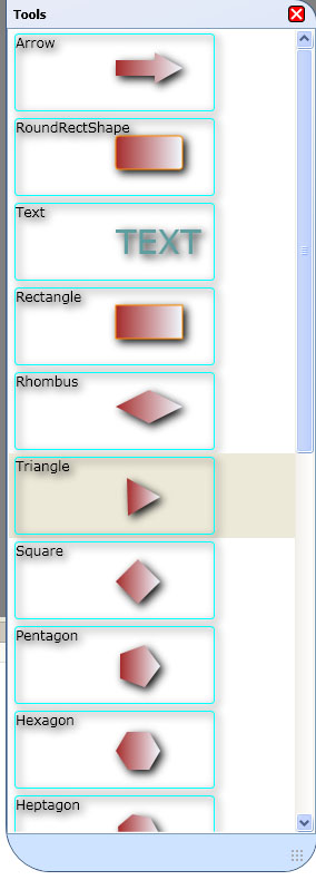
然后用户可以在屏幕上绘制他们选择的形状,如下所示:

然后可以将绘图导出为 XML 文件或 JPG 文件。
<?xml version="1.0" encoding="utf-8"?>
<ShapeList xmlns:xsi="http://www.w3.org/2001/XMLSchema-instance" xmlns:xsd="http://www.w3.org/2001/XMLSchema">
  <ShapeList>
    <LeShape xsi:type="LeRectangle">
      <ShowBorder>true</ShowBorder>
      <LeBorderColor>
        <A>255</A>
        <R>0</R>
        <G>0</G>
        <B>0</B>
      </LeBorderColor>
      <BorderWidth>1</BorderWidth>
      <Rect>
        <X>300</X>
        <Y>157</Y>
        <Width>79</Width>
        <Height>65</Height>
      </Rect>
      <LeFromColor>
        <A>30</A>
        <R>255</R>
        <G>0</G>
        <B>0</B>
      </LeFromColor>
      <LeToColor>
        <A>30</A>
        <R>255</R>
        <G>255</G>
        <B>255</B>
      </LeToColor>
      <LightAngle>225</LightAngle>
      <Fill>true</Fill>
    </LeShape>
    <LeShape xsi:type="RoundRectShape">
      <ShowBorder>true</ShowBorder>
      <LeBorderColor>
        <A>255</A>
        <R>0</R>
        <G>0</G>
        <B>0</B>
      </LeBorderColor>
      <BorderWidth>1</BorderWidth>
      <Rect>
        <X>174</X>
        <Y>230</Y>
        <Width>84</Width>
        <Height>74</Height>
      </Rect>
      <LeFromColor>
        <A>255</A>
        <R>0</R>
        <G>0</G>
        <B>0</B>
      </LeFromColor>
      <LeToColor>
        <A>255</A>
        <R>127</R>
        <G>255</G>
        <B>212</B>
      </LeToColor>
      <LightAngle>225</LightAngle>
      <Fill>true</Fill>
      <Radius>10</Radius>
    </LeShape>
    <LeShape xsi:type="ZoneShape">
      <ShowBorder>true</ShowBorder>
      <LeBorderColor>
        <A>255</A>
        <R>0</R>
        <G>0</G>
        <B>0</B>
      </LeBorderColor>
      <BorderWidth>1</BorderWidth>
      <Rect>
        <X>132</X>
        <Y>97</Y>
        <Width>90</Width>
        <Height>84</Height>
      </Rect>
      <LeFromColor>
        <A>30</A>
        <R>255</R>
        <G>0</G>
        <B>0</B>
      </LeFromColor>
      <LeToColor>
        <A>30</A>
        <R>255</R>
        <G>255</G>
        <B>255</B>
      </LeToColor>
      <LightAngle>225</LightAngle>
      <Fill>true</Fill>
      <TextField>
        <ShowBorder>true</ShowBorder>
        <LeBorderColor>
          <A>255</A>
          <R>0</R>
          <G>0</G>
          <B>0</B>
        </LeBorderColor>
        <BorderWidth>1</BorderWidth>
        <Rect>
          <X>237</X>
          <Y>112</Y>
          <Width>58</Width>
          <Height>22</Height>
        </Rect>
        <LeFromColor>
          <A>30</A>
          <R>255</R>
          <G>0</G>
          <B>0</B>
        </LeFromColor>
        <LeToColor>
          <A>30</A>
          <R>255</R>
          <G>255</G>
          <B>255</B>
        </LeToColor>
        <LightAngle>225</LightAngle>
        <Fill>true</Fill>
        <Caption>Shape 2</Caption>
        <LeTextFont>
          <Size>10</Size>
          <Name>Tahoma</Name>
          <Style>Regular</Style>
        </LeTextFont>
        <LeTextColor>
          <A>255</A>
          <R>255</R>
          <G>0</G>
          <B>0</B>
        </LeTextColor>
        <TextSize>10</TextSize>
      </TextField>
      <Caption>Shape 2</Caption>
    </LeShape>
  </ShapeList>
</ShapeList>
稍后可以使用该 XML 文件通过此项目重新打开,最终用户可以再次编辑他们的绘图。
以下是该项目源代码的解释。
该项目首先使用以下代码在 GUI 上创建一个画布:
<Border Margin="10" CornerRadius="3" Grid.Row="1" Grid.Column="1" Background="Beige">
   <Border.BitmapEffect>
      <DropShadowBitmapEffect />
   </Border.BitmapEffect>
   <Canvas Margin="3" x:Name="DrawingCanvas" Background="AliceBlue" Opacity="1" Visibility="Visible">
   <local:CustomRender Canvas.Top="0" Canvas.Left="0" x:Name="shapeCollection">
    <local:CustomRender.BitmapEffect>
      <DropShadowBitmapEffect />
    </local:CustomRender.BitmapEffect>
   </local:CustomRender>
   </Canvas>
</Border>
上面的代码首先创建一个带有阴影的 Border,Border 位于 Grid 控件内,因此它将填充 Grid 的单元格。Border 内部的内容是一个 Canvas 控件,Canvas 内部只有一个 FrameworkElement,我们的 DLL (CustomRender),它只是一个元素,然后我们使用该元素的 DrawingContext,手动绘制所有形状。DrawingContext 类似于 WinForm 的 Graphics 对象。
我们的 CustomRender 只是一个 FrameworkElement,它只接受 Visual 对象。最重要的是,它实现了以下两个函数:
// Provide a required override for the VisualChildrenCount property.
        protected override int VisualChildrenCount
        {
            get { return childrens.Count; }
        }
       // Provide a required override for the GetVisualChild method.
        protected override Visual GetVisualChild(int index)
        {
            if (index < 0 || index >= childrens.Count)
            {
                throw new ArgumentOutOfRangeException();
            }
            return childrens[index];
        }
然后在我们的代码中,我们只需要将 Visual 对象添加到这个 Visual 对象集合中,.NET Framework 将为我们渲染这个 CustomRender 对象。
我们使用反射将形状添加到我们的控制器类中,首先只创建一个形状,然后将形状的 Visual 对象添加到上面的 CustomRender 类中。
  Point pt = e.GetPosition(myCanvas);

  ConstructorInfo constructor = myTool.GetConstructor(new Type[] { typeof(Point) });
  CurShape = constructor.Invoke(new object[] { pt }) as LeShape;


  shapeCollection.AddObject(CurShape.myVisual);
当我们想要绘制这个形状时,我们可以随时调用以下方法:
  DrawingContext dc = myVisual.RenderOpen();
  Draw(dc);

  if (selected)
  {
     if (bounds.Width > 5 && bounds.Height >5)
     {
         DrawPoints(dc, bounds);
     }
  }
  dc.Close();
DrawingVisual 的 RenderOpen 方法将为我们打开一个 DrawingContext,然后我们可以绘制我们的对象,如果形状被选中,那么我会为它绘制几个跟踪点。完成所有这些操作后,我们必须调用 DrawingContext 的 Close 方法,以告知我们已经完成了此 Visual 的绘制。
这是我的绘图工具的 WPF 版本的原理,如果您感兴趣,也可以在我的 WinForms 版本中获取更多信息。
关注点
在编写代码的过程中,你学到了什么有趣/好玩/令人恼火的东西吗? 你做了什么特别巧妙、疯狂或异想天开的事情吗?
历史
在此处保持您所做的任何更改或改进的实时更新。