
使用Silverlight-5和XNA实现3D基础(第二部分)
4.50/5 (6投票s)
学习使用Silverlight-5和XNA进行3D编程。
引言
这篇入门文章是第二篇,它基于第一篇文章的“Hello World”程序,并通过一系列重构步骤,展示了如何创建一个旋转多面体的 3D 世界。
每个步骤都进行了详细解释,过程中引入了几个新的 XNA 概念,最终的程序应该能为更复杂的 3D 应用提供良好的基础。
如果您还没有阅读第一篇文章,应该先阅读它,因为本文是以它为起点的。您可以在这里找到它。
第一步 - 优化 Draw 事件处理程序
在第一篇文章中,我们创建了最简单的 Silverlight-XNA 程序,包含一个旋转的三角形。为了保持程序小巧,我们将所有代码都放在了 Draw 事件处理程序中,这对于大型程序来说不是一个好方法。
为了使程序可扩展,我们需要将尽可能多的代码移出 Draw 处理程序,使其尽可能快速和高效。
在我们的程序中,我们
- 为
Texture2D、VertexBuffer和BasicEffect对象创建类变量。 - 在
DrawingSurface上创建一个“Loaded”事件处理程序,并将这些对象的设置代码放在里面。
有些东西无法移出 Draw 处理程序。特别是,任何直接影响 GraphicsDevice 状态的操作都必须在 Draw 处理程序中完成,否则您将收到异常。
The GraphicsDevice can only be used when accessed inside a Draw callback
on the render thread.
这包括设置顶点缓冲区和效果,以及更改简单的设置,例如 RasterizerState。限制的原因是 GraphicsDevice 由组合线程“拥有”,因此不允许我们从任何其他线程更改它。注意:“渲染”线程和“组合”线程是同义词。
然而,我们可以从其他线程引用 GraphicsDevice ——我们必须这样做才能创建纹理和顶点缓冲区——我们只是不能更改它。
请注意,我们没有在 Draw 处理程序和 Loaded 处理程序之间实现任何锁定——我们假设 Loaded 处理程序将在 Draw 事件触发之前完成。
这是精简后的 Draw 处理程序。
private void drawingSurface1_Draw(object sender, DrawEventArgs e)
{
  GraphicsDevice g = GraphicsDeviceManager.Current.GraphicsDevice;
  g.RasterizerState = RasterizerState.CullNone;
  g.SetVertexBuffer(vb);

  basicEffect.World = Matrix.CreateRotationY((float)e.TotalTime.TotalSeconds * 2);
  basicEffect.View = Matrix.CreateLookAt(new Vector3(0, 0, 5.0f),
            Vector3.Zero, Vector3.Up);
  basicEffect.Projection = Matrix.CreatePerspectiveFieldOfView
(0.85f, aspectRatio, 0.01f, 1000.0f);

  g.Clear(new Color(0.8f, 0.8f, 0.8f, 1.0f));
  basicEffect.CurrentTechnique.Passes[0].Apply();
  g.DrawPrimitives(PrimitiveType.TriangleList, 0, 1);
  e.InvalidateSurface();
}
这是执行所有一次性设置的 Loaded 处理程序。
private void drawingSurface1_Loaded(object sender,System.Windows.RoutedEventArgs e)
{
  if (Is3dBlocked())
    return;
  GraphicsDevice g = GraphicsDeviceManager.Current.GraphicsDevice;

  VertexPositionNormalTexture[] vertices = new VertexPositionNormalTexture[]{
    new VertexPositionNormalTexture(new Vector3(-1, -1, 0),Vector3.Forward,Vector2.Zero),
    new VertexPositionNormalTexture(new Vector3(0, 1, 0),Vector3.Forward,Vector2.Zero),
    new VertexPositionNormalTexture(new Vector3(1, -1, 0),Vector3.Forward,Vector2.Zero)};
  vb = new VertexBuffer(g, VertexPositionNormalTexture.VertexDeclaration,
            vertices.Length, BufferUsage.WriteOnly);
  vb.SetData(0, vertices, 0, vertices.Length, 0);

  texture = new Texture2D(g, 1, 1, false, SurfaceFormat.Color);
  texture.SetData<Color>(new Color[1] { new Color(1f, 0, 0) });

  basicEffect = new BasicEffect(g);
  basicEffect.EnableDefaultLighting();
  basicEffect.LightingEnabled = true;
  basicEffect.Texture = texture;
  basicEffect.TextureEnabled = true;
}

private bool Is3dBlocked()
{
  if (GraphicsDeviceManager.Current.RenderMode == RenderMode.Hardware)
    return false;
  string message;
  switch (GraphicsDeviceManager.Current.RenderModeReason)
  {
    case RenderModeReason.Not3DCapable:
      message = "You graphics hardware is not capable of displaying this page ";
      break;
    case RenderModeReason.GPUAccelerationDisabled:
      message = "Hardware graphics acceleration has not been enabled
            on this web page.\n\n" +
        "Please notify the web site owner.";
      break;
    case RenderModeReason.TemporarilyUnavailable:
      message = "Your graphics hardware is temporarily unavailable.\n\n" +
        "Try reloading the web page or restarting your browser.";
      break;
    case RenderModeReason.SecurityBlocked:
      message =
        "You need to configure your system to allow this web site
            to display 3D graphics:\n\n" +
        "  1. Right-click the page\n" +
        "  2. Select 'Silverlight'\n" +
        "     (The 'Microsoft Silverlight Configuration' dialog will be displayed)\n" +
        "  3. Select the 'Permissions' tab\n" +
        "  4. Find this site in the list and change its
        3D Graphics permission from 'Deny' to 'Allow'\n" +
        "  5. Click 'OK'\n" +
        "  6. Reload the page";
      break;
    default:
      message = "Unknown error";
      break;
  }
  MessageBox.Show(message, "3D Content Blocked", MessageBoxButton.OK);
  return true;
}
第二步 - 创建一个立方体
现在我们已经优化了渲染,是时候在程序中添加一些实心的 3D 对象了。我们将从一个简单的立方体开始。此时,我们还将介绍“索引缓冲区”。
索引缓冲区是一项可选技术,可以提高性能。如果我们不想使用它们,那么我们将使用 DrawPrimitives() 方法绘制三角形;如果我们想使用它们,我们将使用 DrawIndexedPrimitives() 方法。索引缓冲区可以减少我们发送到 GPU 的顶点数量。其思想是,由于多个三角形通常共享顶点,因此我们可以一次定义唯一的顶点,然后将三角形定义为顶点缓冲区中的索引的简单列表。
一个立方体有六个正方形面,每个面由两个三角形组成,总共十二个三角形,三十六个顶点。此时,您可能会认为使用索引缓冲区可以将顶点数减少到八个。毕竟,一个立方体只有八个角。不幸的是,XNA 顶点定义的内容不仅仅是位置;它还定义了用于计算相邻三角形上的高光和阴影的照明“法线”。照明法线是垂直于 3D 对象表面的单位长度向量。我们的立方体有六个平面,因此法线需要与其垂直。这意味着我们不能共享不同立方体面上三角形之间的顶点。我们确实节省了一些,因为对于每个面,我们可以使用四个顶点而不是六个——总共是二十四个顶点而不是三十六个。
这是我们的顶点定义开头。
VertexPositionNormalTexture[] vertices = new VertexPositionNormalTexture[]
{
  new VertexPositionNormalTexture(new Vector3(-1, 1, 1),Vector3.Forward,Vector2.Zero),
  new VertexPositionNormalTexture(new Vector3(1, 1, 1),Vector3.Forward,Vector2.Zero),
  new VertexPositionNormalTexture(new Vector3(1, -1, 1),Vector3.Forward,Vector2.Zero),
  new VertexPositionNormalTexture(new Vector3(-1, -1, 1),Vector3.Forward,Vector2.Zero),
.
.
.
这是我们使用索引缓冲区定义三角形的方式。
short[] indices = new short[]
  {0,1,2,2,3,0,4,5,6,6,7,4,8,9,10,10,11,8, ... };
ib = new IndexBuffer(g, typeof(short), indices.Length, BufferUsage.WriteOnly);
ib.SetData(indices);
使用四元数进行旋转
以前,我们的三角形以简单的方式围绕 Y 轴旋转。但现在我们有了一个立方体,我们希望它围绕对角线轴旋转,以便展示它所有的面。有几种实现方法,但到目前为止最整洁、最酷的方法是使用 Quaternion 来创建我们的旋转矩阵。
Quaternion 在 XNA 中易于使用,尽管它基于一些相当深入的数学。顺便说一句,它们是在一百多年前发明的,并且在很长一段时间里它们一直处于抽象数学的边缘,没有已知的实际应用——现在它们被广泛用于航天和计算机图形学。
这是我们如何使用 Quaternion 创建对角线旋转。
Vector3 axis = new Vector3(-0.5f, 1, -0.5f);
axis.Normalize();
Quaternion quaternion = Quaternion.CreateFromAxisAngle
            (axis, (float)e.TotalTime.TotalSeconds * 2);
basicEffect.World = Matrix.CreateFromQuaternion(quaternion);
现在我们有了一个旋转的立方体。

第三步 - 将立方体封装到单独的类中
到目前为止,我们将所有代码都放在了 MainPage.xaml.cs 文件中。这对于学习来说很好,但它无法扩展。以我们当前的程序结构,引入第二个旋转立方体甚至是不切实际的。
3D 图形程序代表 3D 对象——它们本质上是面向对象的。现在是时候创建一个 Cube 类了。
我们希望尽可能多地封装立方体的行为和属性,让主程序在全局层面协调事物。
XNA 在这里带来了一些困境,因为效果类,特别是 BasicEffect 类,封装了混合内容:有些是全局的,有些是特定于单个 3D 对象的。灯光设置和相机位置显然是全局的,应该属于主程序,但是顶点缓冲区和纹理肯定需要与每个 3D 对象关联,也许效果的选择也是如此。
这里可能没有唯一的正确答案。因此,基于我们仍然相对简单的程序当前的即时需求,我们将把 Effect 对象封装到我们的立方体类中。我们将假设标准的默认灯光设置,并将相机详细信息传递给我们的立方体类的绘制方法。
我们的 cube 类具有以下 private 数据。
private VertexBuffer vb;
private IndexBuffer ib;
private Texture2D texture;
private BasicEffect be;
private Matrix world;
我们将一个 color 参数传递到构造函数中,我们用它来生成纹理,并公开一个 public 的读/写属性来表示世界变换,以便主程序能够定位或移动类的实例。
我们提供了一个 public Draw 方法供主程序调用。
public void Draw(Matrix view, Matrix projection)
{
  GraphicsDevice g = GraphicsDeviceManager.Current.GraphicsDevice;
  g.SetVertexBuffer(vb);
  g.Indices = ib;

  be.World = world;
  be.View = view;
  be.Projection = projection;

  be.CurrentTechnique.Passes[0].Apply();
  g.DrawIndexedPrimitives(PrimitiveType.TriangleList, 0, 0,
            vb.VertexCount, 0, ib.IndexCount / 3);
}
现在我们的主页可以轻松创建两个立方体。
private void drawingSurface1_Loaded(object sender, System.Windows.RoutedEventArgs e)
{
  cube1 = new SolidColorCube(new Color(1f,0,0));
  cube2 = new SolidColorCube(new Color(0,0,1f));
}
……并绘制和旋转它们。
private void drawingSurface1_Draw(object sender, DrawEventArgs e)
{
  GraphicsDevice g = GraphicsDeviceManager.Current.GraphicsDevice;
  Matrix view = Matrix.CreateLookAt(new Vector3(0, 0, 8.0f), Vector3.Zero, Vector3.Up);
  Matrix projection = Matrix.CreatePerspectiveFieldOfView
            (0.85f, aspectRatio, 0.01f, 1000.0f);

  Vector3 axis = new Vector3(-0.5f, 1, -0.5f);
  axis.Normalize();
  Matrix rotation = Matrix.CreateFromQuaternion
    (Quaternion.CreateFromAxisAngle(axis, (float)e.TotalTime.TotalSeconds * 3));
  cube1.World = rotation * Matrix.CreateTranslation(2, 0, 0);
  cube2.World = rotation * Matrix.CreateTranslation(-2, 0, 0);

  g.Clear(new Color(0.8f, 0.8f, 0.8f, 1.0f));
  cube1.Draw(view, projection);
  cube2.Draw(view, projection);
  e.InvalidateSurface();
}

第四步 - 创建一个通用的多面体类
作为最后一步,我们将进一步扩展,并创建所有五个正多面体的模型。
我们显然可以为每个正多面体创建一个类似于 cube 类的类,但这将会有很多重复的代码,并且手动定义更复杂的实体的三角形网格将非常费力。相反,我们将创建一个通用的 Polyhedron 类,它可以自动对网格进行三角剖分。自动三角剖分在更复杂的 3D 程序中很常见,所以在这里展示一个简单的例子很有用。
这是我们的 Polyhedron 构造函数的签名。
public Polyhedron(Vector3[] corners, int[][] faces, Color color)
我们传入两个数据结构,它们共同以简单、自然的方式定义了多面体的形状。在构造函数内部,我们调用一个辅助方法来对网格进行三角剖分并创建顶点缓冲区(我们在这里不使用索引缓冲区)。
private static VertexPositionNormalTexture[] CreateVertices
            (Vector3[] corners, int[][] faces)
{
  int triangleCount = 0;
  foreach (int[] face in faces)
    triangleCount += face.Length - 2;

  VertexPositionNormalTexture[] vertices =
    new VertexPositionNormalTexture[triangleCount * 3];
  int i = 0;
  foreach (int[] face in faces)
  {
    for (int j = 0; j < face.Length - 2; j++)
    {
      vertices[i++] = new VertexPositionNormalTexture
            (corners[face[0]], Vector3.Zero, Vector2.Zero);
      vertices[i++] = new VertexPositionNormalTexture
            (corners[face[j + 1]], Vector3.Zero, Vector2.Zero);
      vertices[i++] = new VertexPositionNormalTexture
            (corners[face[j + 2]], Vector3.Zero, Vector2.Zero);
    }
    Vector3 vectorA = vertices[i - 1].Position - vertices[i - 3].Position;
    Vector3 vectorB = vertices[i - 1].Position - vertices[i - 2].Position;
    Vector3 normal = Vector3.Cross(vectorB, vectorA);
    for (int j = 0; j < (face.Length - 2) * 3; j++)
      vertices[i - 1 - j].Normal = normal;
  }
  return vertices;
}
这个非常有用的函数代码行数不多,应该能够弄清楚它的工作原理。但有几点值得强调。
计算法线
第一个是,我们使用 Vector3.Cross() 方法来计算每个面的法线向量,我们使用面内的两个任意三角形边传递给 Cross() 方法。用数学语言来说:两个向量的叉积是这两个向量定义的平面的法线。一旦我们计算出某个面的法线,我们就会用计算出的法线更新该面中所有三角形的所有顶点。
三角形顶点顺序
第二个要注意的是,在这种自动生成三角形的代码中,我们需要非常小心地确保每个三角形的顶点顺序正确。在 3D 世界中,三角形有正面和反面,渲染过程需要知道哪个是哪个——照明计算和背面剔除都依赖于此。
XNA 使用“顺时针”约定来定义三角形的正面。换句话说,如果三个顶点按照它们在顶点缓冲区(或索引缓冲区,如果我们正在使用的话)中出现的顺序绕三角形呈顺时针方向,那么我们看到的就是三角形的正面。对于我们的 Polyhedron 类,我们对我们的多面体面采用相同的约定。这确保了正面位于我们实体的外部。
主页
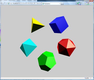
有了通用的polyhedron 类后,我们现在可以通过以简单自然的方式定义它们的几何形状来创建任意数量的不同形状的多面体。五个柏拉图立体的几何定义在 static Polyhedra 类中。我们程序的最后一次增强是,我们的主页现在将 3D 对象保存在一个数组中,以便可以在 Draw 处理程序中遍历它们。
设置代码现在是。
private void drawingSurface1_Loaded
    (object sender, System.Windows.RoutedEventArgs e)
{
  polyhedrons = new Polyhedron[]
  {
    new Polyhedron(Polyhedra.CubeCorners,
        Polyhedra.CubeFaces, new Color(0, 0, 1f)),
    new Polyhedron(Polyhedra.TetrahedronCorners,
        Polyhedra.TetrahedronFaces, new Color(1f, 1f, 0)),
    new Polyhedron(Polyhedra.OctahedronCorners,
        Polyhedra.OctahedronFaces, new Color(0, 1f, 1f)),
    new Polyhedron(Polyhedra.DodecahedronCorners,
        Polyhedra.DodecahedronFaces, new Color(0, 1f, 0)),
    new Polyhedron(Polyhedra.IcosahedronCorners,
        Polyhedra.IcosahedronFaces, new Color(1f, 0, 0))
  };
}
……而绘图代码现在是。
private void drawingSurface1_Draw(object sender, DrawEventArgs e)
{
  GraphicsDevice g = GraphicsDeviceManager.Current.GraphicsDevice;
  Matrix view = Matrix.CreateLookAt(new Vector3(0, 0, 8.0f), Vector3.Zero, Vector3.Up);
  Matrix projection = Matrix.CreatePerspectiveFieldOfView
            (0.85f, aspectRatio, 0.01f, 1000.0f);

  Vector3 axis = new Vector3(-0.5f, 1, -0.5f);
  axis.Normalize();
  Matrix rotate1 = Matrix.CreateFromQuaternion
    (Quaternion.CreateFromAxisAngle(axis, (float)e.TotalTime.TotalSeconds * 3));
  Matrix translate = Matrix.CreateTranslation(2, 0, 0);
  for (int i = 0; i < polyhedrons.Length; i++)
  {
    Matrix rotate2 = Matrix.CreateRotationZ
    (i * MathHelper.TwoPi / 5 + (float)e.TotalTime.TotalSeconds / 3);
    polyhedrons[i].World = rotate1 * translate * rotate2;
  }
  g.Clear(new Color(0.8f, 0.8f, 0.8f, 1.0f));
  foreach (Polyhedron polyhedron in polyhedrons)
    polyhedron.Draw(view, projection);
  e.InvalidateSurface();
}
结论
即使有了所有这些增强功能,整个程序现在也只包含 125 行代码,再加上 150 行用于正多面体的几何定义。这相当令人印象深刻,并且很好地说明了 XNA 的强大功能。