
C/C++ 项目的图形化文档系统
4.93/5 (13投票s)
一个用于创建 C/C++ 项目交互式文档的概念工具
目录
摘要
本文旨在介绍一种新的软件文档创建方法,并描述用于实现本文所揭示概念的 gds 应用程序的结构、功能和内部机制。请注意,该应用程序本身并非旨在成为商业产品或公司工具(尽管它可以作为此类工具使用),而是上述概念的概念性实现。
软件文档的作用
通常,一个软件文档由一个或多个文本和图形文档组成,用于解释软件的结构和工作方式。软件文档的类型有很多,创建方法更是数不胜数(例如:统一过程、Tropos - 面向代理等),其中大多数都是标准化的步骤、细化和框架组合。在不深入研究特定文档系统的情况下,显而易见的是,每种系统都有其优点和缺点,具体取决于其使用的任务。遵循软件文档方法意味着要规划一系列初始步骤,然后继续设计应用程序的组件,这些组件最终将被翻译成纯代码。尽管建模语言、图形和图表可用于描述先前编写的代码项目的最终结构,但标准的建模技术建议在每次打开软件项目时遵循一系列步骤和实践。特别是在从头开始建模一个大型软件时,这是一项复杂的任务,需要对底层架构、API 和可用功能有深入的了解。
理解代码的关键因素
仅仅完美掌握一门语言并不意味着你总能轻易理解使用该语言的文本(或通用图形表示)中表达的含义或概念(这不仅仅适用于编程语言),因此,花费时间研究一个源代码文件以理解该代码实际执行的功能,并将这些操作“在脑海中联系起来”以形成一个更宏大的应用程序的复杂视图,这是完全正常的。描述软件的行为和结构应该能帮助那些将要使用你代码的其他人理解你是如何组织代码的(有多少个模块/你是否遵循了某种模式/等等),以及你项目特定部分的目的。大量注释代码块是良好的编程实践,尽管有时它可能不足以完全取代恰当的文档。只要你真的希望其他人理解你的代码,那么提供关于你的应用程序的功能和工作方式的完整洞察就应该是你的首要目标。一家雇用新程序员并让他们负责一个大型应用程序的特定部分的软件公司,会致力于为他们提供尽可能多的关于该模块如何工作、它应该做什么以及(可能)为什么他们那样设计的尽可能多的信息。程序员越快掌握代码并熟悉它,他们就越快能完全投入使用该代码,并能够修改或扩展它。
清晰有效地解释概念的能力是一种个人技能,因人而异。然而,有一些实践和技术可以极大地简化概念的理解。首先,复杂度级别。如果一个模块非常复杂(即,它由许多其他函数/模块组成,或者执行大量相互关联的操作),那么在正式文档中可能很难描述。一般来说,每个复杂的元素都可以分解成若干个其他部分。例如,我们来看一个简单的程序,它要求输入一个矩阵并返回矩阵中每个数字的平方。
#include <iostream>
using namespace std;
class myMatrix
{
public:
    int rows, columns;
    double *values;
    myMatrix(int height, int width)
    {
        if (height == 0 || width == 0)
            throw "Matrix constructor has 0 size";
        rows = height;
        columns = width;
        values = new double[rows*columns];
    }
    ~myMatrix()
    {
        delete [] values;
    }
    // Allows matrix1 = matrix2
    myMatrix& operator= (myMatrix const& m)
    {
        if(m.rows != this->rows || m.columns != this->columns)
            throw "Size mismatch";
        memcpy(m.values,this->values,this->rows*this->columns*sizeof(double));
    }

    // Allows both matrix(3,3) = value and value = matrix(3,3)
    double& operator() (int row, int column)
    {
        if (row < 0 || column < 0 || row > this->rows || column > this->columns)
            throw "Size mismatch";
        return values[row*columns+column];
    }
};
int main(int argc, char* argv[])
{
    int dimX, dimY;
    cout << "Enter the matrix's X dimension: ";
    cin >> dimX;
    cout << "Enter the matrix's Y dimension: ";
    cin >> dimY;
    myMatrix m_newMatrix(dimY,dimX);
    // Insert all the matrix data
    for(int j=0; j<dimY; j++)
    {
        for(int i=0; i<dimX; i++)
        {
            cout << "Enter the (" << i << ";" << j << ")th element: " << endl;
            cin >> m_newMatrix(j,i);
        }
    }
    // Calculate the square of each number
    for(int j=0; j<dimY; j++)
    {
        for(int i=0; i<dimX; i++)
        {
            m_newMatrix(j,i) = m_newMatrix(j,i)*m_newMatrix(j,i);
        }
    }
    // Print out the new matrix
    cout << endl;
    for(int j=0; j<dimY; j++)
    {
        for(int i=0; i<dimX; i++)
        {
            cout << m_newMatrix(j,i) << "\t";
        }
        cout << endl;
    }
    return 0;
}
有不同级别的细节可以解释这个简单程序的任务和工作方式。就像高级语言可以比低级语言进行更多的抽象一样,第一个高级级别可以用简单简洁的方式解释这个程序的目的。第二个级别可以扩展第一个级别,并提供关于程序结构如何的洞察。额外的第三个级别可以继续第二个级别的工作,并另外扩展每个描述。这个过程可以一直持续到应用程序的代码,它就像最后一个级别,包含了所有必需的信息。代码提供了更详细的信息,但与其它级别相比更复杂。
上述程序可能具有如下级别的结构

在这种情况下,我们选择使用三个级别(加上代码级别)来表示相同的信息,但具有更高和更低(更丰富)的细节,但级别数量可以更多。“更大的细节”的概念几乎在所有软件文档和所有软件设计过程中都是一个基本概念。
在开始处理新的软件代码时,需要考虑的另一个概念是代码块被插入的上下文。程序员花费在搜索程序执行特定操作的代码特定部分的大部分时间,是为了创建一个“心智图”,其中每个块都被归类,并且其在整体架构中的作用得到明确定义。
最后,程序块的执行顺序并不总是显而易见的,尤其是在处理高度多线程代码时。有时,只有仔细阅读才能理解所涉及线程的同步机制。
软件文档的新方法:交互性
使用图形化和交互式方法进行软件文档记录是一个相对较新的概念。由于一个具体的例子胜过千言万语,在本节中,我们将通过一个小型 Qt C++ 程序及其关联的交互式文档来介绍。整个软件包(程序源代码 + 文档目录)可以通过本页面顶部的链接下载。
我们将通过交互式文档来研究的程序很简单:一个在受限笛卡尔坐标区域内的基本线性函数绘制器。

由于这是一个示例(且简单的)应用程序,因此只实现了一个基本的绘图功能,其代码在错误处理和模块化方面肯定不尽如人意。虽然通过通读整个代码不难理解,但如果应用程序更复杂,程序员将花费相当多的时间来理解结构、所有数据类型及其作用、执行流程(如前所述,多线程会阻碍此过程)以及各个模块之间的整体协作。
以下视频展示了 gds 软件如何为简单的图形应用程序生成交互式文档。
 GDS 应用程序的 YouTube 演示视频(用于示例笛卡尔图应用)
深入了解 gds 概念应用
GDS 代表“图形化文档系统”,它是一个概念性的实验应用程序,旨在提供对新软件代码的交互式且极其直观的概述。如果使用得当,gds 可以让程序员为他人创建高度详细的代码文档,以便使用和理解。
前面几节介绍的概念指导了 gds 应用的设计和实现。在本节中,将简要介绍应用程序的使用,之后将介绍应用程序的结构和代码组织。请注意,gds 使用 openGL 渲染,需要 openGL 扩展 3.3 或更高版本才能正常运行。它还需要安装 Microsoft Visual C++ 2010 可再发行组件 x86 包(您可以从 这里免费下载)。
该应用程序有两种主要操作模式
- 查看模式 - 此模式提供三级文档的虚拟游览,建议首次使用代码的用户使用
- 编辑模式 - 此模式允许创建新文档(如果存储所有数据库文件的文档目录不存在)或编辑现有文档
启动应用程序时会提示用户进行选择

查看模式非常直观,有一个代码窗格(级别一不可见 - 每个人都应该能理解它),一个中央图窗格和一个右侧文档窗格。还有一个导航窗格,允许执行三个操作
- 缩小到上一级(级别 1 是用户可以缩小的最大级别)
- 放大到选定的节点(级别 3 是用户可以缩小的最大级别)
- 选择下一个块 - 这对于在代码中导航以及获得代码逻辑中事件发生的精确顺序非常有用。块的顺序可以在编辑模式下设置(我们很快就会看到如何操作)。
以下屏幕分别显示了 gds 应用在级别 1、2 和 3 的查看模式下的情况。


编辑模式允许程序员修改或创建新文档或现有文档。当没有文档时(即,应用程序路径中没有 gdsdata 目录),则没有图,gds 会尝试重新创建它。这可能意味着文档已被移动到其他地方(gds 找不到它),或者还没有文档。
以下是 gds 应用在编辑模式下,未找到文档的情况。

通过“添加子块”按钮,可以向文档添加节点(或根节点,如果没有图)以及标签(块名称)、索引和文档。索引字段用于查看模式按照正确的顺序导航块。如果此索引设置重复或错误,查看模式将只会按照错误的顺序导航。在每个级别,都可以删除一个元素(无论它是根/子/父元素)或将其内容与其他元素交换。
当选中一个节点时,按下“下一级别”按钮将导致 gds 为该节点创建子级别:这意味着块需要有关其工作方式的额外详细信息。gds 会在导航级别或关闭应用程序时自动保存修改的节点。
左侧的代码窗格仅在级别 2 和 3 可见,允许用户选择一个代码文件并在其中高亮显示行。

级别 2 块可能没有关联的代码文件,因此有一个“清除”按钮。请注意,gds 旨在固定位于代码项目根目录中的位置。所有代码文件的路径都存储为相对于 gds 目录。有一些简单的更正算法可以在代码文件移动时找回正确的代码行,但是 gds 应该用于文档化那些打算发布和“准备好”的文件。显然,文档文件也可能被删除,关联的节点将出现“文档文件未找到”的错误,然后允许用户定义新的文档文件。如前所述,这是一个概念性和实验性的应用程序,用于传递新的文档方法,一个拥抱这种理念的商业工具应该将这些功能集成到适当的版本控制系统中(该系统还将跟踪 diff (差异)和移动的文件)。
由于 gds 被设计成一个易于使用的应用程序,因此普通用户无需了解更多即可使用它。
以下章节将更详细地描述 gds 背后的编程逻辑,因此主要面向编程人员或对修改 gds 感兴趣的人(gds 是开源的)。
一个 OpenGL 图形控件
以下部分需要一些基本的 opengL 编程知识 - 建议读者阅读。
QGLDiagramWidget 类是整个 gds 应用程序的主要控件。它是显示 3D 图形并允许渲染树形图的中心窗格。由于应用程序使用 Qt 库,因此该控件是 QGLWidget 类的子类,该类通过提供三个主要的虚拟函数(可以重新实现)来提供绘制 opengL 图形的功能。
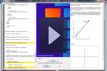
- paintGL() - 这是渲染 opengL 场景的函数,也是控件大部分代码所在的地方
- resizeGL() - 每次控件大小调整时调用
- initializeGL() - 设置 opengL 渲染上下文,在 paintGL 或 resizeGL 之前调用一次
该图控件还使用重绘(参见 Qt 文档了解更多信息),这基本上意味着块名被绘制在 opengL 渲染场景之上,调用重绘并执行重绘的代码如下:
 // Paint event, it's called every time the widget needs to be redrawn and
// allows overpainting over the GL rendered scene
void QGLDiagramWidget::paintEvent(QPaintEvent *event)
{
    makeCurrent();
    // QPainter initialization changes a lot of stuff in the openGL context
    glPushAttrib(GL_ALL_ATTRIB_BITS);
    glMatrixMode(GL_PROJECTION);
    glPushMatrix();
    glMatrixMode(GL_MODELVIEW);
    glPushMatrix();
    // Calls base class which calls initializeGL ONCE and then paintGL each time it's needed
    QGLWidget::paintEvent(event);
    // Don't paint anything if the data isn't ready yet
    if(dataDisplacementComplete)
    {
        // Time for overpainting
        QPainter painter( this );
        painter.setPen(QPen(Qt::white));
        painter.setFont(QFont("Arial", 10, QFont::Bold));
        // Draw the text on the rendered screen
        // -----> x
        // |
        // |
        // | y
        // v
        // Use the bounding box features to create a perfect bounding rectangle to include all the necessary text
        QRectF rect(QPointF(10,this->height()-25),QPointF(this->width()-10,this->height()));
        QRectF neededRect = painter.boundingRect(rect, Qt::TextWordWrap, "Current Block: " + m_selectedItem->m_label);
        if(neededRect.bottom() > this->height())
        {
            qreal neededSpace = qAbs(neededRect.bottom() - this->height());
            neededRect.setTop(neededRect.top()-neededSpace-10);
        }
        painter.drawText(neededRect, Qt::TextWordWrap , "Current Block: " + m_selectedItem->m_label);
        painter.end();
    }
    // Actually draw the scene, double rendering
    swapBuffers();
    // Restore previous values
    glMatrixMode(GL_MODELVIEW);
    glPopMatrix();
    glMatrixMode(GL_PROJECTION);
    glPopMatrix();
    glPopAttrib();
    if(!m_readyToDraw) // If there's still someone waiting to send data to us, awake him
    {
        m_readyToDraw = true;
        qWarning() << "GLWidget ready to paint data";
        if(m_associatedWindowRepaintScheduled)
        {
            qWarning() << "m_associatedWindowRepaintScheduled is set";
            if(m_gdsEditMode)
            {
                qWarning() << "Calling the deferred painting method now..";
                ((MainWindowEditMode*)m_referringWindow)->deferredPaintNow();
            }
            else
            {
                qWarning() << "Calling the deferred painting method now..";
                ((MainWindowViewMode*)m_referringWindow)->deferredPaintNow();
            }
        }
    }
}
代码有详尽的注释,但花几句话进行一些说明可能会有益于理解正在发生的事情。
QGLDiagramWidget 使用双缓冲,这意味着在调用 swapBuffers() 之前,不会显示在 opengL 上下文中渲染的场景。这可以防止颜色拾取模式(我们稍后会对此进行解释)和动画过渡之间的闪烁。
initializeGL() 函数负责初始化 opengL 场景所需的所有资源,即 VBO(虚拟缓冲对象,这是存储要绘制的元素数据的缓冲区,如顶点、uv 纹理坐标、法线和索引)、纹理和着色器。
        // Load, compile and link two shader programs ready to be bound, one with the normal
        // gradient, the other with the selected gradient
        loadShadersFromResources("VertexShader1.vert", "FragmentShader1.frag", &ShaderProgramNormal);
        loadShadersFromResources("VertexShader2Picking.vert", "FragmentShader2Picking.frag", &ShaderProgramPicking);
        // Clear-up VBOs (if VBO don't exist, this simply ignores them)
        freeBlockBuffers();
        // Initialize VBOs for rounded blocks
        initBlockBuffers();
        // Clear-up texture buffers (if they don't exist, this simply ignores them)
        freeBlockTextures();
        // Initialize texture buffers for rounded blocks
        initBlockTextures();
GLwidget 使用一个简单的 3D 模型,其顶点、UV 纹理坐标、法线和索引存储在“roundedRectangle.h”文件中。控件还渲染它并通过编译的着色器程序应用 phong 光照模型(有两对顶点和片段着色器,第一对用于正常绘制元素,第二对用于初始化颜色拾取场景并执行诸如连接器绘制之类的简单操作)。
用于正常渲染对象的顶点着色器如下:
 #version 330 core
// Input vertex data, different for all executions of this shader.
layout(location = 0) in vec3 aVertexPosition;
layout(location = 1) in vec2 aTextureCoord;
layout(location = 2) in vec3 aVertexNormal;
// Values that stay constant for the whole mesh.
uniform mat4 uMVMatrix;
uniform mat4 uPMatrix;
uniform mat3 uNMatrix;
out vec2 vTextureCoord;
out vec3 vTransformedNormal;
out vec4 vPosition;
void main()
{
    // Pass along the position of the vertex (used to calculate point-to-vertex light direction),
    // no perspective here since we need absolute position (we used absolute position for the light point too)
    vPosition = uMVMatrix * vec4(aVertexPosition, 1.0);
    // Set the complete (Perspective*model*view) position of the vertex
    gl_Position =  uPMatrix * vPosition;

    // Save the uv attributes
    vTextureCoord = aTextureCoord;

    // Pass along the modified normal matrix * vertex normal (the uNMatrix is
    // necessary otherwise normals would point in a wrong direction and
    // they would not be modulo 1 vectors), this matrix ensures direction and
    // modulo 1 preservation while converting their coords to absolute coordinates
    vTransformedNormal = uNMatrix * aVertexNormal;
}
有用于接收模型顶点、UV 纹理坐标和法线向量的属性,用于接收透视、模型视图(由模型组成 - 此矩阵设置为元素的初始位置,视图 - 此矩阵默认设置为根元素,但可以通过键盘上的方向箭头更改)和法线矩阵(用于保持单位法线向量的方向和模长)的 uniform(如果您对为什么需要特殊的法线矩阵传递给片段着色器来调整光照感兴趣,可以参考 Eric Lengyel 的“3D 游戏编程和计算机图形学数学”)。顶点着色器基本上只计算新的顶点位置,并将其与 UV 坐标和转换后的法线一起传递给片段着色器。
片段着色器负责计算光照方向(这些着色器使用来自点的每片段光照)和将用于加权光照颜色分量的光照权重向量。最后,它在考虑光照权重的情况下渲染纹理(使用 UV 纹理坐标)。
#version 330 core
// u,v values
in vec2 vTextureCoord;
in vec3 vTransformedNormal;
in vec4 vPosition;
// Values that stay constant for the whole mesh.
uniform sampler2D myTextureSampler;
uniform vec3 uAmbientColor;
uniform vec3 uPointLightingLocation;
uniform vec3 uPointLightingColor;
void main()
{
    vec3 lightWeighting;
    // Get the light direction vector
    vec3 lightDirection = normalize(uPointLightingLocation - vPosition.xyz);
    // Simple dot product between normal and light direction (cannot be lower than zero - no light)
    float directionalLightWeighting = max(dot(normalize(vTransformedNormal), lightDirection), 0.0);
    // Use the phong model
    lightWeighting = uAmbientColor + uPointLightingColor * directionalLightWeighting;

    // Weight the texture color with the light weight
    vec4 fragmentColor;
    fragmentColor = texture2D(myTextureSampler, vec2(vTextureCoord.s, vTextureCoord.t));

    gl_FragColor = vec4(fragmentColor.rgb * lightWeighting, fragmentColor.a);
}
paintGL() 函数是大部分图形工作所在的地方。在初始化视口和几个其他默认值(例如,glClearColor)后,函数可以切换到两种模式:
- 一种颜色拾取模式
- 一种正常渲染模式
颜色拾取是一种图形技术,通常与 opengL 一起使用,以识别场景中被点击的对象。它是一种比 SELECT 拾取更新的技术,并确保与可编程管道的完美集成(另一方面,SELECT 拾取依赖于固定管道)。
基本上,每个对象都被存储为一个“dataToDraw”对象,并被赋予一个唯一的颜色。
 // Initialize static variable to the first color available
unsigned char dataToDraw::gColorID[3] = {0, 0, 0};
// Set a static dark blue background (51;0;123)
float QGLDiagramWidget::m_backgroundColor[3] = {0.2f, 0.0f, 0.6f};
// Constructor to initialize the unique color
dataToDraw::dataToDraw()
{
    m_colorID[0] = gColorID[0];
    m_colorID[1] = gColorID[1];
    m_colorID[2] = gColorID[2];
    gColorID[0]++;
    if(gColorID[0] > 255)
    {
        gColorID[0] = 0;
        gColorID[1]++;
        if(gColorID[1] > 255)
        {
            gColorID[1] = 0;
            gColorID[2]++;
        }
    }
    // Background color is reserved, so don't assign it
    if(gColorID[0] == (QGLDiagramWidget::m_backgroundColor[0]*255.0f)
            && gColorID[1] == (QGLDiagramWidget::m_backgroundColor[1]*255.0f)
                               && gColorID[2] == (QGLDiagramWidget::m_backgroundColor[2]*255.0f))
    {
        // Next time we would have picked right this color, change it
        gColorID[0]++;
    }
}
当用户点击一个对象时,会记录鼠标位置,并且由于原始 opengL 不识别对象作为实体,因此整个场景会以每个网格的唯一颜色进行渲染。然后,从帧缓冲器中读取鼠标点击的点,并将其颜色与每个对象的颜色进行比较,以识别用户点击的对象。
执行此工作的代码片段如下:
 if(m_pickingRunning)
    {
        //**************************************************************************************************//
        //////////////////////////////////////////////////////////////////////////////////////////////////////
        //                      Picking running, load just what's needed to do it                           //
        //////////////////////////////////////////////////////////////////////////////////////////////////////
        //**************************************************************************************************//
        ////////////////////////////////////////////////////////////////////////////////////////////////////
        //  Phase 1: prepare all shaders uniforms, attribute arrays and data to draw rounded rectangles   //
        ////////////////////////////////////////////////////////////////////////////////////////////////////
        // Do the colorpicking first
        currentShaderProgram = ShaderProgramPicking;
        if(!currentShaderProgram->bind())
        {
            qWarning() << "Shader Program Binding Error" << currentShaderProgram->log();
        }
        // Picking mode, simple shaders
        uMVMatrix = glGetUniformLocation(currentShaderProgram->programId(), "uMVMatrix");
        uPMatrix = glGetUniformLocation(currentShaderProgram->programId(), "uPMatrix");
        // Send our transformation to the currently bound shader,
        // in the right uniform
        float gl_temp_data[16];
        for(int i=0; i<16; i++)
        {
            // Needed to convert from double (on non-ARM architectures qreal are double)
            // to float
            gl_temp_data[i]=(float)gl_projection.data()[i];
        }
        glUniformMatrix4fv(uPMatrix, 1, GL_FALSE, &gl_temp_data[0]);
        gl_modelView = gl_view * gl_model;
        // Bind the array buffer to the one with our data
        glBindBuffer(GL_ARRAY_BUFFER, blockVertexBuffer);
        // Give the vertices to the shader at attribute 0
        glEnableVertexAttribArray(0);
        // Fill the attribute array with our vertices data
        glVertexAttribPointer(
                    0,                                  // attribute. Must match the layout in the shader.
                    3,                                  // size
                    GL_FLOAT,                           // type
                    GL_FALSE,                           // normalized?
                    sizeof (struct vertex_struct),      // stride
                    (void*)0                            // array buffer offset
                    );
        // Bind the element array indices buffer
        glBindBuffer(GL_ELEMENT_ARRAY_BUFFER, blockIndicesBuffer);
        // First draw all normal elements, so bind texture normal
        glDisable(GL_TEXTURE_2D);
        glDisable(GL_FOG);
        glDisable(GL_LIGHTING);

        /////////////////////////////////////////////////////////////////////////
        // Phase 2: iterate through all rounded blocks to draw and set for each one its transformation matrix
        /////////////////////////////////////////////////////////////////////////

        // **************
        // WARNING: DISPLACEMENTS ARE ASSUMED TO BE CALCULATED BY NOW, IF NOT THE RENDERING MIGHT CRASH
        // **************
        // Adjust the view by recalling how it was displaced (by the user with the mouse maybe) last time
        adjustView();
        // Draw the precalculated-displacement block elements
        postOrderDrawBlocks(m_diagramData, gl_view, gl_model, uMVMatrix, TextureID);
        // Save the view for the next passing
        gl_previousUserView = gl_view;

        // At this point the picking should be ready (all drawn into the backbuffer)
        // At the end of paintGL swapBuffers is automatically called
        // Picking still running, identify the object the mouse was pressed on
        // Get color information from frame buffer
        unsigned char pixel[3];
        glReadPixels(m_mouseClickPoint.x(), m_mouseClickPoint.y(), 1, 1, GL_RGB, GL_UNSIGNED_BYTE, pixel);
        // If the background was clicked, do nothing
        if(pixel[0] == (unsigned char)(m_backgroundColor[0]*255.0f)
                && pixel[1] == (unsigned char)(m_backgroundColor[1]*255.0f)
                && pixel[2] == (unsigned char)(m_backgroundColor[2]*255.0f))
        {
            m_goToSelectedRunning = false;
            qWarning() << "background selected..";
            m_pickingRunning = false; // Color picking is over
            this->setFocus(); // The event filter will take care of the keyboard hook
        }
        else
        {
            // Something was actually clicked!
            // Now our picked screen pixel color is stored in pixel[3]
            // so we search through our object list looking for the object that was selected
            QVector<dataToDraw*>::iterator itr = m_diagramDataVector.begin();
            while(itr != m_diagramDataVector.end())
            {
                if((*itr)->m_colorID[0] == pixel[0] && (*itr)->m_colorID[1] == pixel[1] && (*itr)->m_colorID[2] == pixel[2])
                {
                    // Flag object as selected
                    // qWarning() << "SELECTED ELEMENT: " << (*itr)->m_label;
                    // Save the selected element
                    m_selectedItem = (*itr);
                    this->setFocus();
                    m_pickingRunning = false; // Color picking is over
                    // Signal our referring class that the selection has changed
然后将选定元素的指针传递回关联的窗口(查看模式或编辑模式),以指示用户已点击了图形上的另一个元素(或同一个元素)。
如果您没有二叉树和 n 叉树的经验,绘制树并非易事。执行树位移的算法如下:
// This function is fundamental, calculates the displacement of each element of the tree
// to show a "nice" n-ary tree on the screen
void QGLDiagramWidget::calculateDisplacement()
{
    // Let's find the tree's maximum depth
    long depthMax = findMaximumTreeDepth(m_diagramData);
    // and set up the various depth levels
    m_depthIntervals.resize(depthMax+1);
    // Now traverse the tree and update displacements, add every found element to the m_diagramDataVector too for an easy access
    postOrderTraversal(m_diagramData);
    // Data is ready to be painted
    dataDisplacementComplete = true;
    if(!m_swapInProgress)
        repaint();
}
void QGLDiagramWidget::postOrderTraversal(dataToDraw *tree)
{
    // Traverse each children of this node
    for(int i=0; i<tree->m_nextItems.size(); i++)
    {
        postOrderTraversal(tree->m_nextItems[i]);
    }
    if(tree->m_nextItems.size() == 0)
    {
        // I found a leaf, displacement-update
        // Y are easy: take this leaf's depth and put it on its Y coord * Y_space_between_blocks
        tree->m_Ydisp = - (tree->m_depth * MINSPACE_BLOCKS_Y);
        // X are harder, I need to put myself at least min_space_between_blocks_X away
        tree->m_Xdisp = m_maximumXreached + MINSPACE_BLOCKS_X;
        // Let's add this leaf to the respective depth list, this will be useful for its parent node
        m_depthIntervals[tree->m_depth].m_allElementsForThisLevel.append(tree->m_Xdisp);
        // Update the maximumXreached with my value
        if(tree->m_Xdisp > m_maximumXreached)
            m_maximumXreached = tree->m_Xdisp;
    }
    else
    {
        // Parent node, displacement-update
        // Y are easy: take this leaf's depth and put it on its Y coord * Y_space_between_blocks
        tree->m_Ydisp = - (tree->m_depth * MINSPACE_BLOCKS_Y);
        // X are harder, I need to put the parent in the middle of all its children
        if(tree->m_nextItems.size() == 1)
        {
            // Just one child, no need for a middle calculation, let's just take the children's X coord
            tree->m_Xdisp = tree->m_nextItems[0]->m_Xdisp;
        }
        else
        {
            // Find minimum and maximum for all this node's children (in the X axis)
            qSort(m_depthIntervals[tree->m_depth+1].m_allElementsForThisLevel.begin(), m_depthIntervals[tree->m_depth+1].m_allElementsForThisLevel.end());
            long min = m_depthIntervals[tree->m_depth+1].m_allElementsForThisLevel[0];
            long max = m_depthIntervals[tree->m_depth+1].m_allElementsForThisLevel[m_depthIntervals[tree->m_depth+1].m_allElementsForThisLevel.size()-1];
            // Let's put this node in the exact middle
            tree->m_Xdisp = (max+min)/2;
        }
        // Let's add this node to the respective depth list, this will be useful for its parent node
        m_depthIntervals[tree->m_depth].m_allElementsForThisLevel.append(tree->m_Xdisp);
        // Update the maximumXreached with my value (if necessary)
        if(tree->m_Xdisp > m_maximumXreached)
            m_maximumXreached = tree->m_Xdisp;
        // Delete the sublevel under my depth, my children are done and they won't be bothering other nodes
        m_depthIntervals[tree->m_depth+1].m_allElementsForThisLevel.clear();
    }
    // However add this node to the m_diagramDataVector
    m_diagramDataVector.append(tree);
}
long QGLDiagramWidget::findMaximumTreeDepth(dataToDraw *tree)
{
    // Simply recurse in post-order inside the tree to find the maximum depth value
    if(tree->m_nextItems.size() == 0)
        return 0;
    else
    {
        int maximumSubTreeDepth = 0;
        for(int i=0; i<tree->m_nextItems.size(); i++)
        {
            long subTreeDepth = findMaximumTreeDepth(tree->m_nextItems[i]);
            if(subTreeDepth > maximumSubTreeDepth)
                maximumSubTreeDepth = subTreeDepth;
        }
        return maximumSubTreeDepth+1; // Plus this node
    }
}
步骤是
- 后序遍历内存中的树(先子节点 -> 后父节点)
- 使用深度信息作为 Y 坐标,使用子节点信息作为 X 坐标

3. 父节点始终居于其子节点之间
结果是树的位移(应用程序早期阶段的屏幕截图)

关于 GLWidget 还有其他可以说的,但上面提到的已经足以理解代码了。
编辑和查看模式 QMainWindow(s)
该项目的另一个重要单元是编辑模式窗口,主要是因为其包含的大量控件和控件。代码在此处也有详尽的注释,因此我们将只关注对完整理解相关的代码部分。查看窗口代码也类似,尽管存在大量细微差异,这将使一次性重构成为一场噩梦(这就是创建两个类的原因)。
默认情况下,编辑模式窗口的构造函数以级别一模式启动。每个级别由一个枚举类型标识,每个对象(即每个块)都有一个关联的 dbDataStructure。核心结构声明可以在“gdsdbreader.h”头文件中找到。
// This file contains core structures, classes and types for the entire gds app
// WARNING: DO NOT MODIFY UNTIL IT'S STRICTLY NECESSARY
#include <QDir>
#include "diagramwidget/qgldiagramwidget.h"
#define GDS_DIR "gdsdata"
enum level {LEVEL_ONE, LEVEL_TWO, LEVEL_THREE};
// The internal structure of the db to store information about each node (each level)
// this will be serialized before being written to file
class dbDataStructure
{
public:
    QString label;
    quint32 depth;
    quint32 userIndex;
    QByteArray data;    // This is COMPRESSED data, optimize ram and disk space, is decompressed
                        // just when needed (to display the comments)
    // The following ID is used to create second-third level files
    quint64 uniqueID;
    // All the next items linked to this one
    QVector<dbDataStructure*> nextItems;
    // Corresponding indices vector (used to store data)
    QVector<quint32> nextItemsIndices;
    // The father element (or NULL if it's root)
    dbDataStructure* father;
    // Corresponding indices vector (used to store data)
    quint32 fatherIndex;
    bool noFatherRoot; // Used to tell if this node is the root (so hasn't a father)
    // These fields will be useful for levels 2 and 3
    QString fileName; // Relative filename for the associated code file
    QByteArray firstLineData; // Compressed first line data, this will be used with the line number to retrieve info
    QVector<quint32> linesNumbers; // First and next lines (next are relative to the first) numbers
    // -- Generic system data not to be stored on disk
    void *glPointer; // GL pointer
    // These operator overrides prevent the glPointer and other non-disk-necessary data serialization
    friend QDataStream& operator<<(QDataStream& stream, const dbDataStructure& myclass)
    // Notice: this function has to be "friend" because it cannot be a member function, member functions
    // have an additional parameter "this" which isn't in the argument list of an operator overload. A friend
    // function has full access to private data of the class without having the "this" argument
    {
        // Don't write glPointer and every pointer-dependent structure
        return stream << myclass.label << myclass.depth << myclass.userIndex << qCompress(myclass.data)
                         << myclass.uniqueID << myclass.nextItemsIndices << myclass.fatherIndex << myclass.noFatherRoot
                            << myclass.fileName << qCompress(myclass.firstLineData) << myclass.linesNumbers;
    }
    friend QDataStream& operator>>(QDataStream& stream, dbDataStructure& myclass)
    {
        //Don't read it, either
        stream >> myclass.label >> myclass.depth >> myclass.userIndex >> myclass.data
                      >> myclass.uniqueID >> myclass.nextItemsIndices >> myclass.fatherIndex >> myclass.noFatherRoot
                         >> myclass.fileName >> myclass.firstLineData >> myclass.linesNumbers;
        myclass.data = qUncompress(myclass.data);
        myclass.firstLineData = qUncompress(myclass.firstLineData);
        return stream;
    }
};
该结构提供字段来存储每个对象的 data(标签、用户索引、用于创建文档结构的唯一索引、富文本压缩数据等),以及不打算存储在磁盘上的 data。这就是为什么有两个流运算符重载,它们负责处理应写入磁盘的内容和不应写入的内容。
此单元的三个主要函数是:
void MainWindowEditMode::tryToLoadLevelDb(level lvl, bool returnToElement)
void MainWindowEditMode::saveCurrentLevelDb()
void MainWindowEditMode::saveEverythingOnThePanesToMemory()
它们的代码相当庞大,但它们大致完成了 gds 存储系统的 70% 的工作。
tryToLoadLevelDb() 函数负责根据我们想探索的级别,从 gds 默认目录(在“gdbsreader.h”中定义)加载数据库文件。“returnToElement”参数指定了函数在从更深级别返回时是否应该选择之前缩放的元素。
saveCurrentLevelDb() 和 saveEverythingOnThePanesToMemory() 分别将所有项目 data 保存到磁盘和内存(通过重新构建 dbDataStructure 树的更新版本)。
所有元素都存储在一个动态的 QVector
// All elements for the current active graph (and relative GL pointers)
    QVector<dbDataStructure*> m_currentGraphElements;
    // The selected element index for the current active graph (this is updated by the openGL widget through a function)
    dbDataStructure* m_selectedElement;
    // These pointers help in finding/creating the next database file while browsing zoom levels
    quint64 m_currentLevelOneID;
    quint64 m_currentLevelTwoID;
该向量仅用于存储指向元素的指针,它们之间的连接(父->子)存储在它们的 dbDataStructure 对象中。
m_currentLevelOneID 和 m_currentLevelTwoID 这两个变量用于跟踪第一个和第二个级别中活动缩放的当前元素(第三个级别没有额外的缩放属性)。
编辑和查看窗口都使用 Qt 的 UI 模板(类似于 Visual Studio 的 DLGTEMPLATEEX所见即所得编辑器),由 Qt Creator 管理。
右侧的富文本区域是一个 textEditorWin 对象,该对象反过来是 QMainWindow 基类的子类。这是必要的,以便在基本控件(一个普通的 QTextEdit 富文本编辑器)上添加工具栏、动作和复杂控件。代码相当直接,除了少量更改外,与 Qt SDK 的富文本编辑器控件相似,因此我们不再赘述。
代码区域(对于编辑和查看窗口)是一个 CodeEditorWidget (QTextEdit 子类),并关联了一个 CppHighlighter (QSyntaxHighlighter 子类) 对象到其 document(),并使用标准的 C/C++ 语法高亮配置进行设置。除了初始化设置外,信号和槽系统(Qt 特有)还提供了一种便捷的方式将行计数器控件与滚动条事件链接。
// Initialization settings
    setReadOnly(true);
    setAcceptRichText(false);
    setLineWrapMode(QTextEdit::NoWrap);
    // Signal to redraw the line counter when our text has changed
    connect(this, SIGNAL(textChanged()), this, SLOT(updateFriendLineCounter()));
    // And to scroll too
    QScrollBar *scroll1 = this->verticalScrollBar();
    QScrollBar *scroll2 = m_lineCounter->verticalScrollBar();
    connect((const QObject*)scroll1, SIGNAL(valueChanged(int)), (const QObject*)scroll2, SLOT(setValue(int)));
    connect(this, SIGNAL(updateScrollBarValueChanged(int)), (const QObject*)scroll2, SLOT(setValue(int)));
mouseReleaseEvent() 重写负责拦截用户点击的块(在普通文本上下文中相当于行)(如果在编辑模式下),以高亮显示代码中的特定行,其行号将存储在
QVector<quint32> m_selectedLines
向量中。每个节点的关联代码(如果有)存储在以下字段中:
// These fields will be useful for levels 2 and 3
    QString fileName; // Relative filename for the associated code file
    QByteArray firstLineData; // Compressed first line data, this will be used with the line number to retrieve info
    QVector<quint32> linesNumbers; // First and next lines (next are relative to the first) numbers
需要注意的是,每个代码块都由其第一行压缩数据和下一行号来标识(第一行之后的行号是相对于第一行存储的)。这是一种简单的处理方法,用于应对缺乏 proper version control system 的情况,而后者应该检查差异并尝试合并版本。在代码中插入标记注释标签也是一种解决方案,但由于我们认为代码不应被弄乱,因此选择了上述方法。
主编辑窗口独有的一个棘手部分如下:
// This method is called by the openGL widget every time the selection is changed on the graph
void *MainWindowEditMode::GLWidgetNotifySelectionChanged(void *m_newSelection)
{
    // First save the right/left pane data for the old selected element
    if(!m_lastSelectedHasBeenDeleted)
    {
        qWarning() << "GLWidgetNotifySelectionChanged.saveEverythingOnThePanesToMemory()";
        saveEverythingOnThePanesToMemory();
    }
    if(m_swapRunning)
    {
        // There's a swap running, swap the selected element with the new selected element
        GLDiagramWidget->m_swapInProgress = true;
        dbDataStructure *m_newSelectedElement;
        // Select our new element
        long m_newSelectionIndex = -1;
        long m_selectedElementIndex = -1;
        int foundBoth = 0;
        for(int i=0; i<m_currentGraphElements.size(); i++)
        {
            if(foundBoth == 2)
                break;
            if(m_currentGraphElements[i]->glPointer == m_newSelection)
            {
                m_newSelectedElement = m_currentGraphElements[i];
                m_newSelectionIndex = i;
                foundBoth++;
            }
            if(m_currentGraphElements[i]->glPointer == m_selectedElement->glPointer)
            {
                m_selectedElementIndex = i;
                foundBoth++;
            }
        }
        // Swap these two structure's data
        QByteArray m_temp = m_newSelectedElement->data;
        m_newSelectedElement->data = m_selectedElement->data;
        m_selectedElement->data = m_temp;
        QString m_temp2 = m_newSelectedElement->fileName;
        m_newSelectedElement->fileName = m_selectedElement->fileName;
        m_selectedElement->fileName = m_temp2;
        m_temp2 = m_newSelectedElement->label;
        m_newSelectedElement->label = m_selectedElement->label;
        m_selectedElement->label = m_temp2;
        long m_temp3 = m_newSelectedElement->userIndex;
        m_newSelectedElement->userIndex = m_selectedElement->userIndex;
        m_selectedElement->userIndex = m_temp3;
        m_temp = m_newSelectedElement->firstLineData;
        m_newSelectedElement->firstLineData = m_selectedElement->firstLineData;
        m_selectedElement->firstLineData = m_temp;
        QVector<quint32> m_temp4 = m_newSelectedElement->linesNumbers;
        m_newSelectedElement->linesNumbers = m_selectedElement->linesNumbers;
        m_selectedElement->linesNumbers = m_temp4;

        // Avoid a recursive this-method recalling when selected element changes: set swapInProgress and avoid repainting
        GLDiagramWidget->clearGraphData();
        updateGLGraph();
        // Data insertion ended, calculate elements displacement and start drawing data
        GLDiagramWidget->calculateDisplacement();
        GLDiagramWidget->m_swapInProgress = false;
    }
    else
    {
        // Select our new element
        for(int i=0; i<m_currentGraphElements.size(); i++)
        {
            if(m_currentGraphElements[i]->glPointer == m_newSelection)
            {
                m_selectedElement = m_currentGraphElements[i];
                break;
            }
        }
    }
    qWarning() << "New element selected: " + m_selectedElement->label;
    // Load the selected element data in the panes, but first clear them
    qWarning() << "GLWidgetNotifySelectionChanged.clearAllPanes() and loadSelectedElementDataInPanes()";
    clearAllPanes();
    loadSelectedElementDataInPanes();
    if(m_swapRunning)
    {
        m_swapRunning = false;
        ui->swapBtn->toggle();
        // Return to the painting widget the new element to be selected (data has been modified)
        return m_selectedElement->glPointer;
    }
    else
        return NULL;
}
当在 opengL 图形上选中一个对象时(颜色拾取模式 - GLWidget),控件会通知其父窗口(编辑或查看模式)选择已更改。然而,编辑窗口还提供了另一项功能:元素交换。当用户按下“交换元素”按钮(这是一个切换按钮)时,系统会将第一个交换项记录为当前选中的项。反过来,当用户选择另一个元素时,它将被标记为“第二个交换项”,然后交换开始。由于 GLWidget 简单地忽略了所有这些,因此交换逻辑由编辑窗口本身处理,这正是上述代码函数中所发生的。如果交换模式不活动,则在 dbDataStructure 中检索选定的图形元素,将选定元素保存到内存,并使用新选定元素的 data 重新加载窗格。
其他棘手的函数
void MainWindowEditMode::on_deleteSelectedElementBtn_clicked()
此槽以三种不同的方式处理“删除选定元素”操作:
- 如果选定的元素是根,则删除整个图。
- 如果选定的元素不是根且没有子节点,则将其删除。
- 如果选定的元素不是根但有子节点,则会提示用户系统是否应删除子节点及其父节点,或通过指针系统将子节点分配给其父节点的父节点。
void MainWindowEditMode::on_addChildBlockBtn_clicked()
此槽处理“添加子块”操作。如果存在名为 m_firstTimeGraphInCurrentLevel 的变量,则图为空,必须创建根元素(无父节点),否则将创建子元素,并将选定元素设置为父节点。
最后,GLWidget 提供函数来控制绘图过程,而无需处理绘制事件的麻烦。
//// This method is called by the openGL widget when it's ready to draw and if there's a scheduled painting pending
void MainWindowViewMode::deferredPaintNow()
{
    // Sets the swapping value to prevent screen flickering (it disables repaint events)
    bool oldValue = GLDiagramWidget->m_swapInProgress;
    GLDiagramWidget->m_swapInProgress = true;
    GLDiagramWidget->clearGraphData();
    updateGLGraph();
    // Data insertion ended, calculate elements displacement and start drawing data
    GLDiagramWidget->calculateDisplacement();
    // Restore the swapping value to its previous
    GLDiagramWidget->m_swapInProgress = oldValue;
    GLDiagramWidget->changeSelectedElement(m_selectedElement->glPointer);
    // We selected an element for the first time (the graph has been loaded), we need to recharge this item's data
    // Load the selected element data in the panes
    loadSelectedElementDataInPanes();
}
首先调用 clearGraphData(),这将清除 GLWidget 中的块向量并调用重绘,然后调用 calculateDisplacement() 来初始化后序遍历和位移计算,最后调用 changeSelectedElement()(如果需要选择的元素与根不同)来选择另一个元素,该元素反过来会指示绘图函数使用不同的渐变纹理来渲染选定的元素。
所有元素之间的连接都在 GLWidget 的 drawConnectionLinesBetweenBlocks() 函数中自动创建,因此主窗口无需显式调用它。
void QGLDiagramWidget::drawConnectionLinesBetweenBlocks()
{
    // This function is going to draw simple 2D lines with the programmable pipeline
    // The picking shaders are simple enough to let us draw a colored line, we'll use them
    ShaderProgramPicking->bind();
    // NOTICE: since each element's model matrix will be multiplied by the vertex inserted in the vertex array
    // to the shader, this uMVMatrix is actually going to be filled with JUST the VIEW matrix. The result will be
    // the same to the shader
    GLuint uMVMatrix = glGetUniformLocation(ShaderProgramPicking->programId(), "uMVMatrix");
    GLuint uPMatrix = glGetUniformLocation(ShaderProgramPicking->programId(), "uPMatrix");
    // Send our transformation to the currently bound shader,
    // in the right uniform
    float gl_temp_data[16];
    for(int i=0; i<16; i++)
    {
        // Needed to convert from double (on non-ARM architectures qreal are double)
        // to float
        gl_temp_data[i]=(float)gl_projection.data()[i];
    }
    glUniformMatrix4fv(uPMatrix, 1, GL_FALSE, &gl_temp_data[0]);
    for(int i=0; i<16; i++)
    {
        // Needed to convert from double (on non-ARM architectures qreal are double)
        // to float
        gl_temp_data[i]=(float)gl_view.data()[i]; // AGAIN: just the view matrix in the uMVMatrix, the result will be the same
    }
    // Set a color for the lines
    glUniformMatrix4fv(uMVMatrix, 1, GL_FALSE, &gl_temp_data[0]);
    GLuint uPickingColor = glGetUniformLocation(ShaderProgramPicking->programId(), "uPickingColor");
    glUniform3f(uPickingColor, 1.0f,0.0f,0.0f);
    // If there's just one element (root and no connections), exit
    if(m_diagramDataVector.size() == 0 || m_diagramDataVector.size() == 1)
        return;
    // Scroll the diagramDataVector and create the connections for each element
    QVector<dataToDraw*>::iterator itr = m_diagramDataVector.begin();
    // Create a structure to contain all the points for all the lines
    struct Point
    {
        float x,y,z;
        Point(float x,float y,float z)
                        : x(x), y(y), z(z)
        {}
    };
    // This will contain all the point-pairs to draw lines
    std::vector<Point> vertexData;
    while(itr != m_diagramDataVector.end())
    {
        // Set the origin coords (this element's coords)
        QVector3D baseOrig(0.0,0.0,0.0);
        // Adjust them by porting them in world coordinates (*model matrix)
        QMatrix4x4 modelOrigin = gl_model;
        modelOrigin.translate((qreal)(-(*itr)->m_Xdisp),(qreal)((*itr)->m_Ydisp),0.0);
        baseOrig = modelOrigin * baseOrig;
        // Get each children of this node (if any)
        for(int i=0; i< (*itr)->m_nextItems.size(); i++)
        {
            dataToDraw* m_temp = (*itr)->m_nextItems[i];
            // Create destination coords
            QVector3D baseDest(0.0, 0.0, 0.0);
            // Adjust the destination coords by porting them in world coordinates (*model matrix)
            QMatrix4x4 modelDest = gl_model;
            modelDest.translate((qreal)(-m_temp->m_Xdisp),(qreal)(m_temp->m_Ydisp),0.0);
            baseDest = modelDest * baseDest;
            // Add the pair (origin;destination) to the vector
            vertexData.push_back( Point((float)baseOrig.x(), (float)baseOrig.y(), (float)baseOrig.z()) );
            vertexData.push_back( Point((float)baseDest.x(), (float)baseDest.y(), (float)baseDest.z()) );
        }
        itr++;
    }
    // We have everything we need to draw all the lines
    GLuint vao, vbo; // VBO is just a memory buffer, VAO describes HOW the data should be interpreted in the VBO
    // Generate and bind the VAO
    glGenVertexArrays(1, &vao);
    glBindVertexArray(vao);
    // Generate and bind the buffer object
    glGenBuffers(1, &vbo);
    glBindBuffer(GL_ARRAY_BUFFER, vbo);
    // Fill VBO with data
    size_t numVerts = vertexData.size();
    glBufferData(GL_ARRAY_BUFFER,                           // Select the array buffer on which to operate
                 sizeof(Point)*numVerts,                    // The total size of the VBO
                 &vertexData[0],                            // The initial data of the VBO
                 GL_STATIC_DRAW);                           // STATIC_DRAW mode
    // set up generic attrib pointers
    glEnableVertexAttribArray(0);
    glVertexAttribPointer(0,                                // Attribute 0 in the shader
                          3,                                // Each vertex has 3 components: x,y,z
                          GL_FLOAT,                         // Each component is a float
                          GL_FALSE,                         // No normalization
                          sizeof(Point),                    // Since it's a struct, x,y,z are defined first, then the constructor
                          (char*)0 + 0*sizeof(GLfloat));    // No initial offset to the data

    // Call the shader to render the lines
    glDrawArrays(GL_LINES, 0, numVerts);
    // "unbind" VAO and VBO
    glBindVertexArray(0);
    glBindBuffer(GL_ARRAY_BUFFER, 0);
}
连接器是通过链接基本的颜色拾取着色器(无纹理或光照计算)并设置 VAO(顶点数组对象)和 VBO(顶点缓冲对象)来存储要用直线连接的顶点来绘制的。VBO 的作用是存储执行操作所需的内存(该操作将由关联的着色器完成),而 VAO 指定数据如何存储在 VBO 中。然而,这些是基本的 opengL 操作。
结论
本文的目标是通过一个实验性的概念应用程序 - gds 来展示一种新的软件文档方法。与其它工程领域相比,软件工程方法学相对较新,因此未来可能还会有许多改进和变化。
坦白说,这项工作也帮助我学习了 opengL 并加强了我的 Qt 知识,同时实现了一个我长期以来一直在思考的旧想法。
参考文献和链接
- Eric Lengyel 的《3D 游戏编程和计算机图形学数学》
- OpenGL 教程 - http://www.opengl-tutorial.org/
- Qt 文档 - http://doc.qt.nokia.com/