
UIX 嵌入式 UI 库简介:M5 Stack Core2 的时钟
5.00/5 (2投票s)
探索我的用户界面库,其中包含一个网络连接时钟的示例
引言
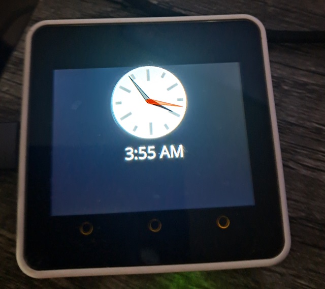
在本文中,我将努力向您介绍UIX(我的用户界面库)和GFX(我基于此构建的图形库)的使用方法。我们将为M5 Stack Core2创建一个简单的时钟。该时钟使用NTP和IP定位服务来获取时间信息。所有操作都是异步的,并且无线电仅在使用时开启。
必备组件
- 一个 M5 Stack Core2 和一根 USB 数据线(已包含在内)
- Visual Studio Code /w PlatformIO
- 一个可以连接2.4Ghz的WiFi路由器
背景
htcw_gfx 图形库的文档和工具可以在这里找到:https://honeythecodewitch.com/gfx
htcw_uix 用户界面库的文档可以在这里找到:https://honeythecodewitch.com/uix
我原本不想编写UIX,因为LVGL已经存在,而且我也没有直接与之竞争的愿望。不过,Espressif通过在ESP32上使用Arduino时破坏了SPI上的SDA读取,迫使我不得不这样做。长话短说,我需要一个按需绘制框架来解决无法从显示器读取帧缓冲区的限制。这是我能够实现诸如alpha混合和抗锯齿等功能的唯一方法。UIX就是我的按需绘制框架。
UIX比LVGL更简单,小部件少得多。它在内存使用方面也更加节约。此外,由于它构建在我的图形库之上,因此可以支持SVG和Truetype等功能。LVGL是C语言,而UIX是C++14和C++17。
基本上,您创建屏幕,然后在这些屏幕上布局控件。UIX会根据需要处理控件的重绘,并且只更新已更改的显示部分。UIX还可以处理触摸反馈,例如按钮。从这个意义上说,它的工作方式类似于LVGL。但我并没有继承LVGL。按需绘制只有一种正确的方法,所以LVGL和我的代码都遵循这种模式。
在这里,我们将使用内置的模拟时钟、一个标签和几个画布控件来构建我们的显示。
使用代码
我们需要做的第一件事是设置我们的platformio.ini文件
[env:m5stack-core2]
platform = espressif32
board = m5stack-core2
framework = arduino
upload_speed=921600
monitor_speed=115200
monitor_filters = esp32_exception_decoder
lib_deps = codewitch-honey-crisis/htcw_m5core2_power ; AXP192 power chip
    codewitch-honey-crisis/htcw_ili9341 ; screen
    codewitch-honey-crisis/htcw_ft6336 ; touch screen panel
    codewitch-honey-crisis/htcw_bm8563 ; real time clock
    codewitch-honey-crisis/htcw_uix ; UI and Graphics
build_unflags = -std=gnu++11
build_flags= -std=gnu++17
    -DBOARD_HAS_PSRAM
upload_port = COM10 ; change this to your configuration
monitor_port = COM10 ; change this to your configuration
前三行是Core 2在Arduino下的样板代码。之后,我们设置上传和监控速度。我添加了esp32异常解码器过滤器,以防崩溃时获得有用的错误消息。
在此之后,是我的代码的许多依赖项。我有一个完整的物联网和嵌入式生态系统。
在此之后,我们将编译器的C++版本更改为GNU C++17,并指示该设备拥有PSRAM,即使我们目前不使用它。
最后,我们有COM端口,您应该根据您的操作系统和硬件配置进行更改。
config.hpp
让我们先看一下include/config.hpp,因为您可能想或需要更改它
#pragma once
static constexpr const char* wifi_ssid = nullptr;
static constexpr const char* wifi_pass = nullptr;
static constexpr const unsigned int wifi_fetch_timeout = 30;
static constexpr const char* time_server_domain = "pool.ntp.org";
static constexpr const unsigned int time_refresh_interval = 10*60;
static const gfx::open_font& text_font = OpenSans_Regular;
在这里,我们有一个空的SSID,表示我们将使用ESP32之前记住的任何WiFi连接。您可以更改它以反映您的网络和凭据。
接下来是获取Internet数据但不成功时的超时时间。这是以秒为单位。
在此之后是NTP服务器地址。我们使用pool.ntp.org。
在此之后是时间刷新间隔(秒)。这是时钟与Internet时间同步的频率。
最后,我们设置字体。此字体从fontsquirrel.com下载,并使用我的生成器工具转换为头文件。GFX和UIX支持大多数Truetype或Opentype字体、Win3.1 FON文件或VLW字体文件。
ui.hpp
include/ui.hpp是我们声明用户界面元素的地方。我通常将它们分成自己的头文件,以便可以在多个地方访问它们。
#pragma once
#include <gfx.hpp>
#include <uix.hpp>
// colors for the UI
using color_t = gfx::color<gfx::rgb_pixel<16>>; // native
using color32_t = gfx::color<gfx::rgba_pixel<32>>; // uix

// the screen template instantiation aliases
using screen_t = uix::screen<gfx::rgb_pixel<16>>;
using surface_t = screen_t::control_surface_type;

// the control template instantiation aliases
using svg_clock_t = uix::svg_clock<surface_t>;
using label_t = uix::label<surface_t>;
using canvas_t = uix::canvas<surface_t>;

// the screen/control declarations
extern screen_t main_screen;
extern svg_clock_t ana_clock;
extern label_t dig_clock;
extern canvas_t wifi_icon;
extern canvas_t battery_icon;
首先,我们包含GFX和UIX库。接下来是一些颜色定义。color<>模板是X11标准中所有颜色的伪枚举,以指定的像素类型表示。我们为本机显示类型(rgb_pixel<16>)和UIX的固有像素类型(始终为rgba_pixel<32>)声明了一个。您可以使用它们来获取命名颜色,例如color_t::purple。
现在我们创建一个别名screen_t,它实例化一个带有rgb_pixel<16>的screen<>模板。让我解释一下。屏幕会生成位图,然后发送到显示器。我们希望它与屏幕的本机像素类型匹配以获得最佳性能,因此通过传入rgb_pixel<16>,我们告诉它以该格式生成位图。
接下来,我们创建一个别名surface_t,它映射到屏幕的control_surface_type。控件表面充当绘图操作的“画布”。在GFX中,这被称为一种“绘制目标”。绘图操作可以定位到此类型。它不是一个简单的位图,但它由一个位图支持。它还将逻辑坐标映射到物理坐标,并可能执行后处理或不同的像素布局(但在本例或大多数情况下不会)。每个控件都需要知道它将绘制到哪种类型的表面,因此我们将为它们提供surface_t的实例化。此别名只是使键入更轻松。
现在我们可以创建我们控件模板实例的别名。我们创建了一个label_t、一个canvas_t和一个svg_clock_t。
最后,我们声明每个控件的实例化(外部)。
对于更大的项目,我还会创建一个ui.cpp并将UI的初始化拆分到该文件中,但对于这个项目,只有几个控件,它并没有增加太多价值,所以它在main.cpp中,我们稍后将介绍。
main.cpp
现在我们将介绍src/main.cpp,所有魔法都在这里发生。
首先,需要很多#includes
#include <Arduino.h>
#include <m5core2_power.hpp>
#include <bm8563.hpp>
#include <ft6336.hpp>
#include <tft_io.hpp>
#include <ili9341.hpp>
#include <uix.hpp>
#include <gfx.hpp>
#include <WiFi.h>
#include <ip_loc.hpp>
#include <ntp_time.hpp>
// font is a TTF/OTF from downloaded from fontsquirrel.com
// converted to a header with https://honeythecodewitch.com/gfx/converter
#define OPENSANS_REGULAR_IMPLEMENTATION
#include <assets/OpenSans_Regular.hpp>
// faWifi icon generated using https://honeythecodewitch.com/gfx/iconPack
#define ICONS_IMPLEMENTATION
#include <assets/icons.hpp>
// include this after everything else except ui.hpp
#include <config.hpp>
#include <ui.hpp>
值得注意的是资源。这些是从网上获取的,并通过我的网站上提供的在线工具生成的。它们已被转换为头文件,以便将内容嵌入固件中。特别是对于字体,这一点很重要。尝试从闪存或SD卡读取它们(虽然支持),但渲染速度通常会非常慢,尽管它们可以从这些来源加载到PSRAM中,然后从那里使用。
继续,我们导入一些常用的命名空间
// namespace imports
using namespace arduino;
using namespace gfx;
using namespace uix;
接下来,我们声明电源管理。这对于Core 2正常运行是必需的。
// for AXP192 power management (required for core2)
static m5core2_power power;
现在事情变得有点复杂,因为我们正在声明硬件总线连接——在这种情况下是SPI,然后将该总线实例传递给我们的LCD控制器驱动程序——在这种情况下是ILI9342c,这是Core 2使用的。这设置了总线的引脚、DMA大小和要使用的SPI主机,然后将其传递给驱动程序。所有引脚都是硬编码的,因为它们永远不会改变。最后,我们实例化lcd_t驱动程序。
// for the LCD
using tft_bus_t = tft_spi_ex<VSPI,5,23,-1,18,0,false,32*1024+8>;
using lcd_t = ili9342c<15,-1,-1,tft_bus_t,1>;
static lcd_t lcd;
接下来是我们用于刷新显示器的两个32KB字节数组
// use two 32KB buffers (DMA)
static uint8_t lcd_transfer_buffer1[32*1024];
static uint8_t lcd_transfer_buffer2[32*1024];
UIX使用这些来创建我之前提到的控件表面的后备位图。之所以有两个,是因为我们正在使用DMA,因此UIX将写入一个,而另一个正在传输。DMA不是必需的,如果不使用,我们可以有一个两倍大的缓冲区。但是,使用DMA可以获得更好的吞吐量。另一方面,较小的传输缓冲区可能意味着某些控件需要多次重绘才能完全渲染。这是拆东墙补西墙。然而,在这里,我们最大的控件是128x128(16位颜色),即32KB,所以我们不需要更大的。
在这个项目中,我们不使用触摸屏,但由于它是UIX的一个重要组成部分,我认为至少应该给出一个接线示例。第一步是声明它。在Core 2上,它位于第二个I2C总线(Wire1)上。
// for the touch panel
using touch_t = ft6336<280,320>;
static touch_t touch(Wire1);
现在,我们来看用于保持时间及相关任务的所有内容
// for the time stuff
static bm8563 time_rtc(Wire1);
static char time_buffer[32];
static long time_offset = 0;
static ntp_time time_server;
static bool time_fetching=false;
第一行定义了实时时钟硬件驱动程序。第二行我们用来存储数字时钟的字符串。UIX不复制字符串。它使用您提供的指针,因此您需要根据需要分配这些字符串的空间。
time_offset是UTC偏移量(秒)。本质上,这是我们的时区。
time_server存储NTP服务管理器。
time_fetching指示我们当前是否正在从Internet获取时间信息。只要无线电开启,它就开启。
现在,我们来定义UI屏幕和控件
// the screen/control definitions
screen_t main_screen(
    {320,240},
    sizeof(lcd_transfer_buffer1),
    lcd_transfer_buffer1,
    lcd_transfer_buffer2);
svg_clock_t ana_clock(main_screen);
label_t dig_clock(main_screen);
canvas_t wifi_icon(main_screen);
canvas_t battery_icon(main_screen);
在这里,我们传入屏幕的大小、传输缓冲区的大小(本例中为两个,但每个必须相同大小),然后是一个或两个传输缓冲区(这里我们使用两个)。
再次,之所以使用两个缓冲区,是为了充分利用DMA,以便UIX可以在MCU传输一个缓冲区时绘制另一个缓冲区。
其余的只是我们的控件,与main_screen关联。
接下来,我们有我们的例程,它们基本上将UIX连接到我们的硬件驱动程序。
// for dumping to the display (UIX)
static void lcd_flush(const rect16& bounds,const void* bmp,void* state) {
    // wrap the void* bitmap buffer with a read only (const) bitmap object
    // this is a light and fast op
    const const_bitmap<decltype(lcd)::pixel_type> cbmp(bounds.dimensions(),bmp);
    // send what we just created to the display
    draw::bitmap_async(lcd,bounds,cbmp,cbmp.bounds());
}
// for display DMA (UIX/GFX)
static void lcd_wait_flush(void* state) {
    // wait for any async transfers to complete
    lcd.wait_all_async();
}
// for the touch panel
static void lcd_touch(point16* out_locations,size_t* in_out_locations_size,void* state) {
    // UIX supports multiple touch points. so does the FT6336 so we potentially
    // have two values
    *in_out_locations_size = 0;
    uint16_t x,y;
    if(touch.xy(&x,&y)) {
        Serial.printf("xy: (%d,%d)\n",x,y);
        out_locations[0]=point16(x,y);
        ++*in_out_locations_size;
        if(touch.xy2(&x,&y)) {
            Serial.printf("xy2: (%d,%d)\n",x,y);
            out_locations[1]=point16(x,y);
            ++*in_out_locations_size;
        }
    }
}
基本上,第一个函数负责将我们生成的位图数据发送到显示器。第二个函数负责等待DMA传输完成。第三个例程将我们的触摸设备连接到UIX的触摸系统。我们在这个项目中不使用它,但我觉得应该包含它,因为它非常基础。
现在,我们来看更多特定于应用程序而不是特定于硬件的方法。
// updates the time string with the current time
static void update_time_buffer(time_t time) {
    tm tim = *localtime(&time);
    strftime(time_buffer, sizeof(time_buffer), "%I:%M %p", &tim);
    if(*time_buffer=='0') {
        *time_buffer=' ';
    }
}
此例程基本上格式化12小时制的时钟字符串。它使用strftime()但对其进行了修改,以删除任何前导零。请注意,time_buffer是全局的。UIX对内存非常吝啬,就像GFX一样,它通常期望您自己提供内存。文本也不例外。当您设置UIX控件的文本时,它会直接使用您提供的指针,而不会复制。因此,您需要将该指针在屏幕刷新期间保持有效。
接下来的两个例程绘制我们的画布,它们基本上只是图标。UIX没有图标控件,所以我们只使用一个画布并自己绘制它。
static void wifi_icon_paint(surface_t& destination, const srect16& clip, void* state) {
    // if we're using the radio, indicate it with the appropriate icon
    if(time_fetching) {
        draw::icon(destination,point16::zero(),faWifi,color_t::light_gray);
    }
}
static void battery_icon_paint(surface_t& destination, const srect16& clip, void* state) {
    // display the appropriate icon for the battery level
    // show in green if it's on ac power.
    int pct = power.battery_level();
    auto px = power.ac_in()?color_t::green:color_t::white;
    const const_bitmap<alpha_pixel<8>>* ico;
    if(pct<25) {
        ico = &faBatteryEmpty;
        if(!power.ac_in()) {
            px=color_t::red;
        }
    } else if(pct<50) {
        ico = &faBatteryQuarter;
    } else if(pct<75) {
        ico = &faBatteryHalf;
    } else if(pct<100) {
        ico = &faBatteryThreeQuarters;
    } else {
        ico = &faBatteryFull;
    }
    draw::icon(destination,point16::zero(),*ico,px);
}
主要的复杂性在于根据电池电量选择正确的图标。否则,我们只是从include/assets/icons.hpp绘制图标。该文件是使用我的图标包工具生成的。
setup()
此例程很长,所以我们将分段介绍。
Serial.begin(115200);
power.initialize(); // do this first
lcd.initialize(); // do this next
touch.initialize();
touch.rotation(0);
time_rtc.initialize();
Serial.println("Clock booted");
我们基本上只是初始化设备,然后指示已启动。
// init the screen and callbacks
main_screen.background_color(color_t::black);
main_screen.on_flush_callback(lcd_flush);
main_screen.wait_flush_callback(lcd_wait_flush);
main_screen.on_touch_callback(lcd_touch);
在这里,我们设置了回调函数。如果希望UIX正常工作,正确连接所有这些非常重要。它不一定需要触摸,但如果您使用DMA,请务必正确设置回调函数并实现它们,就像我们所做的那样。否则可能会导致死机、黑屏等各种问题。
接下来,我们初始化控件,从模拟时钟开始。请注意,每个控件都必须使用register_control()显式注册到其屏幕。
// init the analog clock, 128x128
ana_clock.bounds(srect16(0,0,127,127).center_horizontal(main_screen.bounds()));
ana_clock.face_color(color32_t::light_gray);
// make the second hand semi-transparent
auto px = ana_clock.second_color();
// use pixel metadata to figure out what half of the max value is
// and set the alpha channel (A) to that value
px.template channel<channel_name::A>(
    decltype(px)::channel_by_name<channel_name::A>::max/2);
ana_clock.second_color(px);
// do similar with the minute hand as the second hand
px = ana_clock.minute_color();
// same as above, but it handles it for you, using a scaled float
px.template channelr<channel_name::A>(0.5f);
ana_clock.minute_color(px);
main_screen.register_control(ana_clock);
我们主要是设置属性。bounds()很重要,它接受一个srect16(带有16位坐标值的有符号矩形),它告诉UIX控件在屏幕上的位置。通常,在初始化控件时,即使您计划稍后移动它,也应始终设置它。
我们在这里注意的一件事是,时钟是128x128(16位颜色),正好是32KB,这并非巧合,它与我们的每个传输缓冲区大小相同。如果它更大,时钟就需要绘制多次才能渲染完成。它是SVG。SVG不轻巧。它很花哨,很复杂,并且有代价。将时钟保持在传输缓冲区的大小内可以大大提高性能。
否则,我们正在获取和设置颜色。请注意,无论您的显示器本机像素类型如何,UIX都使用32位RGBA像素(RGBA8888),因此我们使用color32_t伪枚举以rgba_pixel<32>格式获取颜色。
需要注意的是,我们在两个地方进行了alpha混合。这意味着我们使时钟的某些部分半透明。这就像设置RGBA像素(或任何具有alpha通道的像素格式)的alpha(A)通道一样简单。在第一种情况下,我们获取second_color()(默认为红色),用于秒针。然后我们设置alpha通道。我们希望将其设置为最大值的一半,即127,但我们不是使用硬编码值,而是查询像素的元数据以获取alpha通道(A)并获得其最大值,然后除以二得到结果,然后使用它来设置px的alpha通道。我们本来可以直接使用127,但这不够直观。本质上,alpha通道表示不透明度,其中0完全透明,通道的位深度表示完全不透明的值(这也是默认值)。对于我们的像素,alpha通道是8位(32位的1/4),即0-255。将其设置为127实际上使其仅半透明。这意味着秒针下方的颜色会部分透过。
在第二个地方,我们对分针进行了alpha混合。我们使用了一种性能稍低(但打字容易得多!)的变体来将像素的alpha通道设置为一半。我们使用channelr<>()而不是channel<>()来将值作为介于0(最小值)和1(最大值,在此情况下解析为255)之间的缩放实数来访问。
这两种方法都进行了相同的alpha混合,但方式略有不同,后者要简洁得多。
最后,我们注册控件。如果您忘记此步骤,它将永远不会出现在屏幕上,也不会响应触摸输入。
接下来,我们初始化数字时钟部分,这只是一个标签。
// init the digital clock, 128x40, below the analog clock
dig_clock.bounds(
    srect16(0,0,127,39)
        .center_horizontal(main_screen.bounds())
        .offset(0,128));
update_time_buffer(time_rtc.now()); // prime the digital clock
dig_clock.text(time_buffer);
dig_clock.text_open_font(&text_font);
dig_clock.text_line_height(35);
dig_clock.text_color(color32_t::white);
dig_clock.text_justify(uix_justify::top_middle);
main_screen.register_control(dig_clock);
我们只提供了我们的缓冲区和显示文本所需的信息。请注意,我们在此处更新了时间缓冲区。这样,当控件首次显示时,它就有有意义的内容可显示。
现在,我们设置我们的画布图标控件。这些都很简单,所以我们一起介绍。
// set up a custom canvas for displaying our wifi icon
wifi_icon.bounds(
    srect16(spoint16(0,0),(ssize16)wifi_icon.dimensions())
        .offset(main_screen.dimensions().width-
            wifi_icon.dimensions().width,0));
wifi_icon.on_paint_callback(wifi_icon_paint);
main_screen.register_control(wifi_icon);

// set up a custom canvas for displaying our battery icon
battery_icon.bounds(
    (srect16)faBatteryEmpty.dimensions().bounds());
battery_icon.on_paint_callback(battery_icon_paint);
main_screen.register_control(battery_icon);
基本上,我们只是设置了边界、回调函数,然后注册。边界的计算部分基于它们包含的图标的宽度和高度。
setup()到此结束。
loop()
抛开连接和获取部分,loop()相当简单,但首先让我们介绍一下不简单的那部分——连接和获取业务。
///////////////////////////////////
// manage connection and fetching
///////////////////////////////////
static int connection_state=0;
static uint32_t connection_refresh_ts = 0;
static uint32_t time_ts = 0;
IPAddress time_server_ip;
switch(connection_state) {
    case 0: // idle
    if(connection_refresh_ts==0 || millis() >
        (connection_refresh_ts+(time_refresh_interval*1000))) {
        connection_refresh_ts = millis();
        connection_state = 1;
        time_ts = 0;
    }
    break;
    case 1: // connecting
        time_fetching = true;
        wifi_icon.invalidate();
        if(WiFi.status()!=WL_CONNECTED) {
            Serial.println("Connecting to network...");
            if(wifi_ssid==nullptr) {
                WiFi.begin();
            } else {
                WiFi.begin(wifi_ssid,wifi_pass);
            }
            connection_state =2;
        } else if(WiFi.status()==WL_CONNECTED) {
            connection_state = 2;
        }
        break;
    case 2: // connected
        if(WiFi.status()==WL_CONNECTED) {
            Serial.println("Connected.");
            connection_state = 3;
        } else if(WiFi.status()==WL_CONNECT_FAILED) {
            connection_refresh_ts = 0; // immediately try to connect again
            connection_state = 0;
            time_fetching = false;
        }
        break;
    case 3: // fetch
        Serial.println("Retrieving time info...");
        connection_refresh_ts = millis();
        // grabs the timezone offset based on IP
        ip_loc::fetch(nullptr,nullptr,&time_offset,nullptr,0,nullptr,0);
        WiFi.hostByName(time_server_domain,time_server_ip);
        connection_state = 4;
        time_ts = millis(); // we're going to correct for latency
        time_server.begin_request(time_server_ip);
        break;
    case 4: // polling for response
        if(time_server.request_received()) {
            const int latency_offset = (millis()-time_ts)/1000;
            time_rtc.set((time_t)(time_server.request_result()+
                time_offset+latency_offset));
            Serial.println("Clock set.");
            // set the digital clock - otherwise it only updates once a minute
            update_time_buffer(time_rtc.now());
            dig_clock.invalidate();
            connection_state = 0;
            Serial.println("Turning WiFi off.");
            WiFi.disconnect(true,false);
            time_fetching = false;
            wifi_icon.invalidate();
        } else if(millis()>time_ts+(wifi_fetch_timeout*1000)) {
            Serial.println("Retrieval timed out. Retrying.");
            connection_state = 3;
        }
        break;
}
如果我们不以异步方式处理,那么编码会简单得多,但在连接和获取过程中,它将无法响应,这可能需要几秒钟。为了保持流程的进行,我们将过程分解成步骤,并使用由connection_state驱动的简单状态机来运行这些步骤。请注意static变量,它们在 successive calls to loop()之间保持其状态,这一点很重要。
第一个步骤/状态是空闲状态0。当处于此状态时,我们只是检查时间刷新间隔是否已过。如果是,则移至状态1。
状态1开始尝试连接到WiFi网络,然后移至状态2。
在状态2中,我们等待连接成功或失败,然后根据情况移至状态3或返回状态0。
在状态3中,我们根据当前IP获取时区,然后开始查询NTP服务器。请注意,我们在此处保留一个时间戳,因为稍后需要它。我们移至状态4。
在状态4中,我们等待NTP响应或超时。如果超时,我们移至状态3,重试获取。如果成功,我们设置RTC时钟,更新数字时钟显示,并关闭WiFi。
整个过程中,我们跟踪time_fetching,因此将其状态与无线电的状态(开启或关闭)联系起来。
现在,我们来看更简单的部分——更新我们的UI信息。
///////////////////
// update the UI
//////////////////
time_t time = time_rtc.now();
ana_clock.time(time);
// only update every minute (efficient)
if(0==(time%60)) {
    update_time_buffer(time);
    // tell the label the text changed
    dig_clock.invalidate();
}
// update the battery level
static int bat_level = power.battery_level();
if((int)power.battery_level()!=bat_level) {
    bat_level = power.battery_level();
    battery_icon.invalidate();
}
static bool ac_in = power.ac_in();
if((int)power.battery_level()!=ac_in) {
    ac_in = power.ac_in();
    battery_icon.invalidate();
}
这里发生了几件事。首先,我们获取当前时间,并用它来更新模拟时钟。它只在实际更改时重绘,所以这样做不会触发重绘,除非有必要。对于后面的项目,情况并非如此简单。
标签不知道time_buffer的内容何时发生变化。我们必须自己invalidate()标签以强制重绘,但我们只需要每60秒(整点)这样做一次。这比在每次loop()迭代时强制重绘要好得多,因为那样会非常慢。Truetype字体的渲染成本很高。
对于电池电量,我们只想偶尔触发重绘——当它发生变化时。实际上,我们只在它发生足够大的变化以至于改变图标时才重绘,但这会增加复杂性,而没有带来太多价值。
如果Core 2插入或拔掉了USB电源,我们还需要触发电池图标的重绘。在某些情况下,这会导致第二次无效化,但这没关系,因为UIX会合并重叠的脏矩形,所以这只会导致一次无效化。
最后几行代码很简单,但需要一些解释。此代码中的所有内容都已“协作式多线程”,这意味着每个部分都会做一点工作,然后将控制流传递给下一个任务,而不是一次性完成长时间运行的任务。这会导致应用程序运行更流畅。但是,各种对象需要在loop()中被“泵送”,以便它们能够处理下一单位的工作。我们在这里为NTP服务器、主屏幕和触摸屏驱动程序这样做。触摸屏需要一些特殊的考虑,因为它不喜欢更新太快,否则会导致I2C读取错误和误触。因此,我们每50毫秒只读取一次。
//////////////////////////
// pump various objects
/////////////////////////
time_server.update();
main_screen.update();
// FT6336 chokes if called too quickly
static uint32_t touch_ts = 0;
if(millis()>touch_ts+50) {
    touch_ts = millis();
    touch.update();
}
我不会涵盖IP定位或NTP客户端代码,因为我已经在之前的文章中介绍过了。
历史
- 2024年5月8日 - 初始提交