
将 .3ds 模型转换为 XAML 资源以用于 WPF 3D 场景
4.77/5 (15投票s)
本教程介绍如何将 3D Studio 模型文件 (.3ds) 转换为 XAML 资源,以便在 WPF 3D 客厅场景中使用。
引言
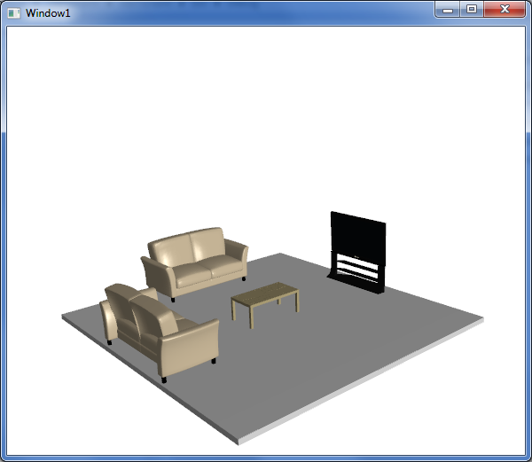
在本文中,我将以创建一个简单的 3D 场景(一个带有两个沙发、一张咖啡桌和一台电视的客厅)为前提,介绍
- 场景基础:视口、灯光、地板和家具容器
- 连接虚拟轨迹球,以便我们可以全面检查场景
- 将模型从 .3ds 转换为 XAML
- 整理 XAML 以便作为资源使用
- 在场景中添加、调整大小和定位模型
背景
两年前,我们开始研究在 WPF 中使用 3D 组件。我找到了大量关于 WPF 3D 基础知识(主要是使用图元)的信息,但在一个关键点上遇到了极其困难:如何将 3D 艺术家创建的模型用于 WPF?当时(并且在很大程度上仍然是),建模师不会在 XAML 中创建 3D 资产——3D 建模工具似乎在采用 XAML 作为支持格式方面进展缓慢。当时,我们使用 DirectX 进行 3D 操作,我们的大部分模型都是 .x 格式的,但即使是更普遍的格式,如 .3ds,也必须先转换为 XAML 才能在 WPF 中使用。
今天,如果您搜索如何从 .3ds 转换为 XAML,您会找到一些有用的工具和示例,但即使是这些,我认为也存在不足,因为我看到的每个转换器都会将场景导出到 XAML,而不是模型。有什么区别?场景包含视口、相机、灯光和模型。如果您只想创建一个带有单个 3D 模型 3D 场景,这非常棒。但如果您想创建一个由多个 3D 模型组成的场景呢?您不希望每个模型都带有自己的视口、相机和灯光。而且,如果您想将这些模型用作资源,以便在一个场景中有多个模型呢?这些是我将在本文中介绍的主题。
步骤 1:创建项目并设置场景
第一步是创建一个项目来托管我们的场景。这个例子没有什么特别之处,在 WPF 教程方面,这已经是相当成熟的领域了。创建项目后,我们将需要添加任何 WPF 3D 场景的关键元素:视口、相机和灯光。由于本教程更侧重于将 .3ds 模型用作资源,因此我将略过此步骤,因为设置的这部分在其他文章中已经很好地介绍了。我包含了一个方向光和一个聚光灯,以在整体场景中增加一些反射效果。
<Window x:Class="_3dsToXaml.Window1"
xmlns="http://schemas.microsoft.com/winfx/2006/xaml/presentation"
xmlns:x="http://schemas.microsoft.com/winfx/2006/xaml"
xmlns:inter3D="clr-namespace:_3DTools;assembly=3DTools"
Title="Window1" Height="500" Width="600"
x:Name="MainWindow">
<Grid>
<Viewport3D x:Name="viewport" RenderOptions.CachingHint="Cache" ClipToBounds="True" >
<Viewport3D.Camera>
<PerspectiveCamera x:Name="myPerspectiveCamera" FarPlaneDistance="300"
	LookDirection="0,0,-1" UpDirection="0,1,0" NearPlaneDistance="1"
	Position="0,3,25" FieldOfView="45">
<PerspectiveCamera.Transform>
<MatrixTransform3D>
</MatrixTransform3D>
</PerspectiveCamera.Transform>
</PerspectiveCamera>
</Viewport3D.Camera>

<ModelVisual3D x:Name="viewportLightsModelVisual3D">
<ModelVisual3D.Content>
<Model3DGroup>
<AmbientLight x:Name="ambientLight" Color="#666666"/>
<DirectionalLight x:Name="directionalLight" Color="#444444" Direction="0 -1 -1">
</DirectionalLight>
<SpotLight x:Name="spotLight" Color="#666666" Direction="0 0 -1"
	InnerConeAngle="30" OuterConeAngle="60" Position="0 1 30" >
</SpotLight>
</Model3DGroup>
</ModelVisual3D.Content>
</ModelVisual3D>
</Viewport3D>

</Grid>
</Window>
此时运行项目不会有趣,因为我们还没有添加任何东西可看!由于我们将要创建的场景最终将是客厅,所以让我们创建一个图元来代表我们的地板。
<ModelUIElement3D x:Name="Floor" >
<GeometryModel3D>
<GeometryModel3D.Geometry>
<MeshGeometry3D x:Name="floorGeometry" Positions="{Binding FloorPoints3D,
	ElementName=MainWindow}" TriangleIndices="{Binding FloorPointsIndices,
	ElementName=MainWindow}" />
</GeometryModel3D.Geometry>
<GeometryModel3D.Material>
<MaterialGroup>
<DiffuseMaterial Brush="LightGray"/>
<SpecularMaterial Brush="LightGray" SpecularPower="100"/>
</MaterialGroup>
</GeometryModel3D.Material>
<GeometryModel3D.BackMaterial>
<DiffuseMaterial Brush="Black"/>
</GeometryModel3D.BackMaterial>
</GeometryModel3D>
</ModelUIElement3D>
您会注意到 MeshGeometry3D 的 Positions 和 TriangleIndices 是通过绑定获得的。没有理由不能在 XAML 中直接创建这些值,但我发现通过代码读取/创建这些值更容易(并且希望您也能更容易地理解)。
public Point3DCollection FloorPoints3D
{
get
{
double x = 6.0; // floor width / 2
double z = 6.0; // floor length / 2
double floorDepth = -0.2; // give the floor some depth so it's not a 2 dimensional plane

Point3DCollection points = new Point3DCollection(20);
Point3D point;
//top of the floor
point = new Point3D(-x, 0, z);// Floor Index - 0
points.Add(point);
point = new Point3D(x, 0, z);// Floor Index - 1
points.Add(point);
point = new Point3D(x, 0, -z);// Floor Index - 2
points.Add(point);
point = new Point3D(-x, 0, -z);// Floor Index - 3
points.Add(point);
//front side
point = new Point3D(-x, 0, z);// Floor Index - 4
points.Add(point);
point = new Point3D(-x, floorDepth, z);// Floor Index - 5
points.Add(point);
point = new Point3D(x, floorDepth, z);// Floor Index - 6
points.Add(point);
point = new Point3D(x, 0, z);// Floor Index - 7
points.Add(point);
//right side
point = new Point3D(x, 0, z);// Floor Index - 8
points.Add(point);
point = new Point3D(x, floorDepth, z);// Floor Index - 9
points.Add(point);
point = new Point3D(x, floorDepth, -z);// Floor Index - 10
points.Add(point);
point = new Point3D(x, 0, -z);// Floor Index - 11
points.Add(point);
//back side
point = new Point3D(x, 0, -z);// Floor Index - 12
points.Add(point);
point = new Point3D(x, floorDepth, -z);// Floor Index - 13
points.Add(point);
point = new Point3D(-x, floorDepth, -z);// Floor Index - 14
points.Add(point);
point = new Point3D(-x, 0, -z);// Floor Index - 15
points.Add(point);
//left side
point = new Point3D(-x, 0, -z);// Floor Index - 16
points.Add(point);
point = new Point3D(-x, floorDepth, -z);// Floor Index - 17
points.Add(point);
point = new Point3D(-x, floorDepth, z);// Floor Index - 18
points.Add(point);
point = new Point3D(-x, 0, z);// Floor Index - 19
points.Add(point);

return points;
}
}

public Int32Collection FloorPointsIndices
{
get
{
int[] indices = new int[] { 0, 1, 2, 0, 2, 3, 4, 5, 7, 5, 6, 7, 8, 9,
	11, 9, 10, 11, 12, 13, 15, 13, 14, 15, 16, 17, 19, 17, 18, 19 };
return new Int32Collection(indices);
}
}
如果现在运行项目,您将拥有一个只有地板的 3D 场景——但您只能看到当前相机的地板视角。我们需要一种方法来移动相机,以便我们可以更全面地探索场景并从不同角度查看它。最常见的方法是通过“虚拟轨迹球”。幸运的是,有一个 CodePlex 项目(3DTools),它几乎可以轻松地添加虚拟轨迹球。
xmlns:_3DTools ="clr-namespace:_3DTools;assembly=3DTools"
<_3DTools:TrackballDecorator Height="Auto">
<_3DTools:Interactive3DDecorator>
<Viewport3D … >
…
</Viewport3D>
</_3DTools:Interactive3DDecorator>
</_3DTools:TrackballDecorator>
步骤 1 的最后一部分是创建一个容器,我们可以将家具添加到其中。稍后我们将回到这一点。
<Window x:Class="_3dsToXaml.Window1"
xmlns="http://schemas.microsoft.com/winfx/2006/xaml/presentation"
xmlns:x="http://schemas.microsoft.com/winfx/2006/xaml"
xmlns:inter3D="clr-namespace:_3DTools;assembly=3DTools"
Title="Window1" Height="500" Width="600"
x:Name="MainWindow"

>
<Grid>
<inter3D:TrackballDecorator x:Name="inter3d" DockPanel.Dock="Bottom" Height="Auto">
<inter3D:Interactive3DDecorator>
<Viewport3D x:Name="viewport" RenderOptions.CachingHint="Cache" ClipToBounds="True" >
<Viewport3D.Camera>
…
</Viewport3D.Camera>

<ContainerUIElement3D x:Name="FurnitureContainer" />

<ModelUIElement3D x:Name="Floor" >
…
</ModelUIElement3D>

<ModelVisual3D x:Name="viewportLightsModelVisual3D">
…
</ModelVisual3D>
</Viewport3D>
</inter3D:Interactive3DDecorator>
</inter3D:TrackballDecorator>

</Grid>
</Window>
步骤 2:获取一些 [免费] 专业模型 (.3ds) 并将其转换为 XAML
现在我们可以为场景获取模型了。在此示例中,我们将添加家具模型。网上有大量免费模型,您可以在此处找到一个很好的搜索网站列表。我为我们的客厅选择了一张沙发、一张咖啡桌和一台电视,并从此处下载了模型(.3ds 格式)。
下载 .3ds 格式的模型后,我们就可以开始将其转换为 XAML 以便在项目中使用。在撰写本文时,我知道有 3 种工具可以将 .3ds 模型转换为 XAML:Electric Rain 的Zam3D、Right Hemisphere 的Deep Exploration,以及 Andrej Benedik 编写的Viewer3ds。根据您使用的工具,模型转换过程可能会略有不同。为了本文的目的,我将使用 Zam3D——这是我最熟悉的工具,并且有一个功能齐全的试用版。
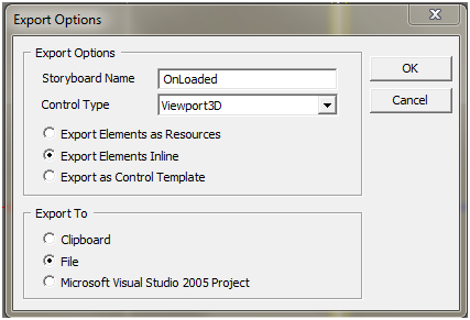
在 Zam3D 中,从文件菜单选择“New from 3DS…”并找到您刚刚下载的 .3ds 模型文件(我们先从 Sofa 模型开始)。然后从文件菜单选择“Export Scene to XAML…”选择 Viewport3D 作为 Control Type,并选择 Export Elements Inline(参见步骤 2 图 1)。
步骤 3:将 XAML 模型转换为资源
我们现在已经成功将 .3ds 格式的沙发模型转换为 XAML,但该 XAML 尚未完全准备好供我们使用。为什么?因为正如我在本文开头提到的,转换过程会创建一个场景(视口、相机、灯光和模型),而我们只需要模型——我们已经为场景创建了视口、相机和灯光。所以我们必须打开 XAML 文件并手动删除这些冗余的元素,只留下 Model3Dgroup。步骤 3 图 1 显示了未编辑的 XAML,步骤 3 图 2 显示了在删除了多余元素后 XAML 应有的样子。
<Viewport3D x:Name="ZAM3DViewport3D" ClipToBounds="true" Width="400"
	Height="300" xmlns=http://schemas.microsoft.com/winfx/2006/xaml/presentation
	xmlns:x=http://schemas.microsoft.com/winfx/2006/xaml
	xmlns:d=http://schemas.microsoft.com/expression/interactivedesigner/2006
	xmlns:c=http://schemas.openxmlformats.org/markup-compatibility/2006
	c:Ignorable="d">
<Viewport3D.Camera>
<PerspectiveCamera x:Name="FrontOR7" FarPlaneDistance="460"
	LookDirection="0,0,-1" UpDirection="0,1,0" NearPlaneDistance="190"
	Position="-7.62939e-006,52.9203,328" FieldOfView="39.5978" />
</Viewport3D.Camera>

<ModelVisual3D>
<ModelVisual3D.Content>
<Model3DGroup x:Name="Scene"> <!-- Scene (XAML Path = ) -->
<Model3DGroup.Transform>
<Transform3DGroup>
<TranslateTransform3D OffsetX="0" OffsetY="0" OffsetZ="0"/>
<ScaleTransform3D ScaleX="1" ScaleY="1" ScaleZ="1"/>
<RotateTransform3D>
<RotateTransform3D.Rotation>
<AxisAngleRotation3D Angle="0" Axis="0 1 0"/>
</RotateTransform3D.Rotation>
</RotateTransform3D>
<TranslateTransform3D OffsetX="0" OffsetY="0" OffsetZ="0"/>
</Transform3DGroup>
</Model3DGroup.Transform>
<AmbientLight Color="#646464" />
<DirectionalLight Color="#FFFFFF" Direction="-0.612372,-0.5,-0.612372" />
<DirectionalLight Color="#FFFFFF" Direction="0.612372,-0.5,-0.612372" />
<Model3DGroup x:Name="Group01OR10">
<!—This is the main Model3Dgroup, we can remove everything around this -->
</Model3DGroup>
</Model3DGroup>
</ModelVisual3D.Content>
</ModelVisual3D>
</Viewport3D>
<Model3DGroup x:Name="Group01OR10">
<!—This is the main Model3Dgroup, we can remove everything around this -->
</Model3DGroup>
现在我们已经将 XAML 文件精简到只剩下 Model3Delement,我们就可以将其转换为资源了。将其设为资源,我们实现了:
- 将模型 XAML 与场景/窗口 XAML 分开
- 我们可以重用场景中的模型或其他场景,而无需复制粘贴
我们将使 XAML 文件成为可用的资源字典,方法是:
- 用
ResourceDictionary元素包装Model3DGroupXML - 使用
x:Key标识符命名Model3DGroup资源 - 删除
Model3DGroupXAML 中所有多余的x:Name标识符
以上 a 和 b 步骤相当直接,无需进一步解释(参见步骤 3 图 3)。c 步骤是必需的,因为 Zam3D 会为我们的主 Model3DGroup 的所有子元素命名。资源不能通过 Name 标识,必须通过 Key 标识,但我们不需要直接引用任何这些子元素,因此我们可以删除所有子 Name 属性。*
*您可以使用 Visual Studio 快速删除所有这些 Name 属性。使用查找->替换,在查找内容中输入 x:Name=”*”,替换为空,然后在查找选项下,选择使用:通配符。
<ResourceDictionary xmlns="http://schemas.microsoft.com/winfx/2006/xaml/presentation"
xmlns:x="http://schemas.microsoft.com/winfx/2006/xaml">
<Model3DGroup x:Key="sofa" >
<!— x:Name attributes have been removed from all child elements -->
</Model3DGroup>
</ResourceDictionary>
使我们的 XAML 模型(ResourceDictionary)准备好使用的最后一步是将其添加到我们的 App.xaml 中,以便在应用程序启动时加载它(参见步骤 3 图 4)。
<Application x:Class="_3dsToXaml.App"
xmlns="http://schemas.microsoft.com/winfx/2006/xaml/presentation"
xmlns:x="http://schemas.microsoft.com/winfx/2006/xaml"
StartupUri="Window1.xaml">
<Application.Resources>
<ResourceDictionary>
<ResourceDictionary.MergedDictionaries>
<ResourceDictionary Source="Models\sofa.xaml"/>
<ResourceDictionary Source="Models\table.xaml"/>
<ResourceDictionary Source="Models\tv.xaml"/>
</ResourceDictionary.MergedDictionaries>
</ResourceDictionary>
</Application.Resources>
</Application>
步骤 4:创建模型基类并将其添加到场景
为了使用我们新创建的模型资源,我们需要一个 3D 元素来显示它们。UIElement3D 非常适合此目的。我们可以简单地创建一个新的 UIElement3D 对象,并将其 VisualModel3D 属性设置为我们资源的内容。由于我们将为每个模型资源执行此操作,因此我创建了一个 UIElement3D 派生类来封装此功能(参见步骤 4 图 1)。基类中还包含“Move”方法,我们将用它来在添加模型到场景后正确地定位它们(关于 Move 方法将在步骤 5 中详细介绍)。
class ModelBase : UIElement3D
{
public ModelBase(string resourceKey)
{
this.Visual3DModel = Application.Current.Resources[resourceKey] as Model3DGroup;
Debug.Assert(this.Visual3DModel != null);
}

public void Move(double offsetX, double offsetY, double offsetZ, double angle)
{
Transform3DGroup transform = new Transform3DGroup();
RotateTransform3D rotateTrans = new RotateTransform3D();
rotateTrans.Rotation = new AxisAngleRotation3D(new Vector3D(0, 1, 0), angle);
TranslateTransform3D translateTrans = new TranslateTransform3D(offsetX, offsetY, offsetZ);
transform.Children.Add(rotateTrans);
transform.Children.Add(translateTrans);
this.Transform = transform;
}
}
有了基类定义后,将模型添加到场景就变得相当直接了。您可能还记得在步骤 1 中,我们在主窗口 XAML 中创建了一个 ContainerUIElement3D 来存放我们的家具。要将模型添加到场景,我们只需创建一个 ModelBase 对象并将其添加到 ContainerUIElement3D(步骤 4 图 2)。
private void CreateScene()
{
ModelBase sofa1 = new ModelBase("sofa");
this.FurnitureContainer.Children.Add(sofa1);

ModelBase sofa2 = new ModelBase("sofa");
this.FurnitureContainer.Children.Add(sofa2);

ModelBase table = new ModelBase("table");
this.FurnitureContainer.Children.Add(table);

ModelBase tv = new ModelBase("tv");
this.FurnitureContainer.Children.Add(tv);
}
现在,我们的场景包含地板、两张沙发、一张桌子和一台电视——一个像样的客厅。但是,我们还没有将模型移动到正确的位置。更糟糕的是,我们不知道这些模型的相对比例。如果我们现在运行场景,我们会看到一堆重叠的家具在地板上,大小不一。是时候清理和完成我们的场景了。
步骤 5:模型与场景清理
完成客厅场景的第一步是缩放模型,使其尺寸合理。那么模型有多大呢?答案是,这取决于。在 WPF 3D 中,所有单位都是相对的。我们的沙发可能看起来非常大,而桌子小到您根本看不见。这完全取决于
- 建模师在创建模型时使用的数字
- 我们创建视口和相机时使用的数字
如果我们从不同的艺术家那里获取模型,并且在设置视口和相机之前对坐标没有任何先验知识,那么在调整比例以使其看起来合理之前,事情很可能会显得完全不对。幸运的是,我们每个模型的 XAML 中的根 Model3DGroup 已经定义了一个 Transform,并且有一个包含 ScaleTransform 的 Transform3DGroup。为了使模型看起来尺寸正确,我们只需要尝试 x、y 和 z 比例的各种值,直到找到合适的比例大小(我们希望均匀缩放,以免扭曲模型)。
<ResourceDictionary xmlns="http://schemas.microsoft.com/winfx/2006/xaml/presentation"
xmlns:x="http://schemas.microsoft.com/winfx/2006/xaml">
<Model3DGroup x:Key="sofa" >
<Model3DGroup.Transform>
<Transform3DGroup>
<TranslateTransform3D OffsetX="0" OffsetY="0" OffsetZ="0"/>
<ScaleTransform3D ScaleX="0.023" ScaleY="0.023" ScaleZ="0.023"/>
<RotateTransform3D>
<RotateTransform3D.Rotation>
<AxisAngleRotation3D Angle="0" Axis="0 1 0"/>
</RotateTransform3D.Rotation>
</RotateTransform3D>
<TranslateTransform3D OffsetX="0" OffsetY="0" OffsetZ="0"/>
</Transform3DGroup>
</Model3DGroup.Transform>
…
</Model3DGroup x:Key="sofa" >
</ResourceDictionary>
一旦缩放正确,唯一要做的事情就是将模型放置在地板上,使其看起来像一个合适的客厅。我们已经在 ModelBase 类中添加了一个 Move 函数,该函数将负责应用平移和旋转变换(即在地板上移动模型并旋转其以面向正确的方向)。由于我们希望所有的家具都在地板上,而不是漂浮在空中或埋在地里,我们只需要关注应用正确的 x 和 z 平移* 以及绕 y 轴的正确旋转。
* 这假设模型作者在正 y 方向上创建了所有组件(即模型原点位于模型的底部,而不是中间)。 一些模型也以 y 为中心,在这种情况下,它们需要 y 平移才能显得在地面上。
private void CreateScene()
{
ModelBase sofa1 = new ModelBase("sofa");
this.FurnitureContainer.Children.Add(sofa1);//adds the first sofa to the middle of the floor
// move to the back edge of the floor
// This would be a -6 Z translation, but that would put the center
// of the sofa along the back edge.
// We want the back of the sofa along the back edge so we have to
// subtract half the depth of the sofa (roughly 1.2)
sofa1.Move(0, 0, -4.8, 0);

ModelBase sofa2 = new ModelBase("sofa");
this.FurnitureContainer.Children.Add(sofa2);//adds the second sofa to the middle of the floor
// rotate and move to the left edge of the floor
sofa2.Move(-4.8, 0, 0, 90);

ModelBase table = new ModelBase("table");
this.FurnitureContainer.Children.Add(table);

ModelBase tv = new ModelBase("tv");
this.FurnitureContainer.Children.Add(tv);
tv.Move(5.5, 0, 0, -90);
}
结论
恭喜您使用转换为 XAML 资源的 .3ds 文件创建了一个功能齐全的 WPF 3D 场景,并包含虚拟轨迹球功能。希望您觉得本文很有用。如果您觉得没有用,请创建一个 WPF 3D 湖景并跳进去吧!:)
历史
- 2010 年 3 月 2 日 - 初稿