WPF 几何图形,处理方式
5.00/5 (32投票s)
使用绘图/绘制器空间范式轻松创建图形
目录
引言
为什么视觉艺术家和数据可视化专家如此喜欢 Processing,而 WPF 可以做得更好?
这就是我买一本关于 Processing 的书时想回答的问题……以下是我的发现。
- Processing 只专注于绘图,它通过限制其范围来简化用户的操作(即使理论上你可以做任何事情,但用它来创建一个完整的应用程序会过于繁琐)。
- Processing 在开箱即用的情况下,区分了绘图空间和绘制器空间。
对于第一点我无能为力。C# 是关于通用开发的,并且应该保持如此。
但是,对于第二点,我脑海中闪过一个想法:如果我们能用这种绘图/绘制器空间范式在 WPF 中绘制几何图形呢?
绘图/绘制器空间范式
使用绘图/绘制器空间范式,在纸上绘制一条 45 度、长度为 10 的直线的方法是,将纸张旋转 45 度,然后绘制一条长度为 10 的直线。
在仅绘图空间范式下,您将使用三角学规则计算直线的第二个点的坐标:end.X = COS(45) * 10,end.Y = SIN(45) * 10。
然后绘制到该点。
对于更复杂的图形,这意味着什么?
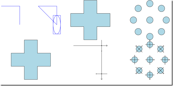
使用仅绘图空间范式绘制那个十字,您需要指定所有坐标。
在纯 XAML 中,大致是这样的。
<Path x:Name="path" Data="M 0 0 L 5 0 L 5 -5 L 10 -5 L 10 0 L 15 0
                          L 15 5 L 10 5 L 10 10 L 5 10 L 5 5 L 0 5 Z"
        Stretch="Uniform"
        Fill="LightBlue"
        Stroke="Black"   ></Path>
另一方面,使用绘图/绘制器空间范式,您只需通过移动画笔和旋转纸张来指定如何绘制它。
在这里,我只指定了我的手和纸张移动来绘制它。
我向前移动 5,然后将纸张旋转 -90 度,然后向前移动 5,然后旋转 90 度,然后向前移动 5,然后旋转 90 度,依此类推。
在 XAML 中
<Path local:GeometryProperties.Data="L 5 ROT -90 L 5 ROT 90 L 5 ROT 90
                                        L 5 ROT -90 L 5 ROT 90 L 5 ROT 90
                                        L 5 ROT -90 L 5 ROT 90 L 5 ROT 90
                                        L 5 ROT -90 L 5 ROT 90 L 5 ROT 90 F Z"
        Stretch="Uniform"
        Fill="LightBlue"
        Stroke="Black"   ></Path>
当您进行旋转时,您旋转的不是图形,而是您正在绘制的纸张……我称之为绘制器空间,与纸张空间(或绘图空间)相对。
现在让我们看一个更难的例子
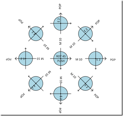
使用仅绘图空间范式,要绘制以下几何图形,您需要指定每个椭圆的坐标。这意味着您需要使用您早已遗忘的三角学。
您能不使用三角学绘制相同的东西吗?当然可以。
使用绘图/绘制器空间范式,您可以说:
- 保存基准,移动 10,绘制椭圆,加载基准,旋转 45
- 重复 7 次
您可以看到我在绘制椭圆时显示了绘制器的基准……正如您所见,绘制器的基准是旋转的。
在这个新的迷你语言中,代码效率很高,如下所示:(Push 和 Pop 用于保存和加载当前/最后的基准)
<Path x:Name="path" local:GeometryProperties.Data="F E 20
                                        ROT 45 PUSH M 100 E 20 POP
                                        ROT 45 PUSH M 100 E 20 POP
                                        ROT 45 PUSH M 100 E 20 POP
                                        ROT 45 PUSH M 100 E 20 POP
                                        ROT 45 PUSH M 100 E 20 POP
                                        ROT 45 PUSH M 100 E 20 POP
                                        ROT 45 PUSH M 100 E 20 POP
                                        ROT 45 PUSH M 100 E 20 POP"
        Stretch="Uniform"
        Fill="LightBlue"
        Stroke="Black"   ></Path>
是不是很简单?
ProcessingContext
我将最重要的类命名为引发此想法的名称。
重要的是,ProcessingContext 上的每个方法都会修改我们在构造函数中传递的 GeometryGroup。
public ProcessingContext(GeometryGroup group)
{
    _Path = new PathGeometry();
    _Geometries = group;
    _Geometries.Children.Add(_Path);
}
Origin 是绘制器空间的起点,而 _CurrentTransform 是将点从绘图坐标转换为绘制器坐标的方式。(我将在稍后深入讨论这一点。)
迷你语言
几乎每个操作都映射到迷你语言。
[GeometryCommand("S")]
public void Scale(double factor)
{
    this.PushTransform(new ScaleTransform(factor, factor)
    {
        CenterX = _Origin.X,
        CenterY = _Origin.Y
    });
}
这意味着“S 2.0”将被解释为 Scale(2.0);
您可以通过 ProcessingContext.Execute(string data) 执行迷你语言。
然后,编写一个附加属性用于 Shape 就相对容易了。
public class GeometryProperties
{
    public static string GetData(DependencyObject obj)
    {
        return (string)obj.GetValue(DataProperty);
    }

    public static void SetData(DependencyObject obj, string value)
    {
        obj.SetValue(DataProperty, value);
    }

    // Using a DependencyProperty as the backing store for Data.
    // This enables animation, styling, binding, etc...
    public static readonly DependencyProperty DataProperty =
        DependencyProperty.RegisterAttached("Data", typeof(string),
        typeof(GeometryProperties), new PropertyMetadata(null, OnDataChanged));

    static void OnDataChanged(DependencyObject source, DependencyPropertyChangedEventArgs args)
    {
        var path = source as Path;
        GeometryGroup pathGeometry = source as GeometryGroup;
        if(path != null)
        {
            pathGeometry = new GeometryGroup();
            path.Data = pathGeometry;
        }

        if(pathGeometry != null)
        {
            var processing = new ProcessingContext(pathGeometry);
            processing.Execute(args.NewValue as string);
        }
    }
}
所以,这是迷你语言的摘要(您可以在源代码中找到示例),所有参数都相对于绘制器的基准。
M x y? | 从原点移动空间 |
L x y? stroked? | 绘制一条线,并移动基准 |
ROT deg | 从原点旋转基准 |
S x y? | 从原点缩放基准 |
PUSH | 保存当前基准 |
POP | 加载最后一次推送的基准 |
BASIS size | 绘制当前基准 |
BEZ x y xControl yControl, stroked | 绘制贝塞尔曲线并以 x y 为基准移动 |
E xRadius yRadius? | 绘制椭圆 |
R xRadius yRadius? xcornRadius? ycornRadius? | 绘制具有圆角的矩形 |
C | 图形将闭合 |
NC | 图形将不闭合 |
F | 图形将填充 |
NF | 图形将不填充 |
Z | 新图形 |
深入探讨,矩阵的力量
如您所见,ProcessingContext 类包含一个 _CurrentTransform, 这个变换可以来回变换任何点,在绘图空间和绘制器空间之间。每次基准变换都会改变 _CurrentTransform,它本质上就是一个 Transform(内部包含一个 Matrix)。
[GeometryCommand("ROT")]
public void Rotate(double degree)
{

    var rotation = new RotateTransform(degree)
    {
        CenterX = _Origin.X,
        CenterY = _Origin.Y
    };
    this.PushTransform(rotation);
}

private void PushTransform(Transform transform)
{
    Append(transform.Value);
    _Origin = _CurrentTransform.Transform(new Point(0, 0));
}

private void Append(Matrix matrix)
{
    var currentMatrix = _CurrentTransform.Value;
    currentMatrix.Append(matrix);
    _CurrentTransform = new MatrixTransform(currentMatrix);
}
使用此 _CurrentTransform,我可以安全地将所有参数从绘制器空间转换为绘图空间,创建一个段,然后平移基准。
[GeometryCommand("L")]
public LineSegment Line(double x, double y, bool stroked)
{
    var nextPoint = _CurrentTransform.Transform(new Point(x, y));
    var line = new LineSegment(nextPoint, stroked);
    this.CurrentFigure.Segments.Add(line);
    Translate(x, y);
    return line;
}
private void Translate(double x, double y)
{
    var t = _CurrentTransform.Transform(new Point(x, y));
    PushTransform(new TranslateTransform(t.X - _Origin.X, t.Y - _Origin.Y));
}
那么 Push 和 Pop 在做什么?它们只是保存基准……
[GeometryCommand("PUSH")]
public void PushMatrix()
{
    _Matrixes.Push(_CurrentTransform.Value);
}

[GeometryCommand("POP")]
public void PopMatrix()
{
    _CurrentTransform = new MatrixTransform(_Matrixes.Pop());
    _Origin = _CurrentTransform.Transform(new Point(0, 0));
}
这就是我对实现的全部说明……我只是将坐标从一个系统转换为另一个系统,并使用以绘制器原点为中心的默认变换……
再给您一个例子
[GeometryCommand("BEZ")]
public BezierSegment Bezier(int x, int y, int controlX, int controlY, bool stroked = true)
{
    var nextPoint = _CurrentTransform.Transform(new Point(x, y));
    var controlPoint = _CurrentTransform.Transform(new Point(controlX, controlY));
    var bezier = new BezierSegment(_Origin, controlPoint, nextPoint, stroked);
    this.CurrentFigure.Segments.Add(bezier);
    Translate(x, y);
    return bezier;
}
代码非常简洁,使用正确的抽象来处理任务,使事情变得如此简单。
结论
Processing 确实是创建强大视觉效果的好方法……但对于了解通用语言的开发人员来说,它的唯一优势在于其绘图范式。
当我阅读一篇关于 OpenGL 中的相机的文章时,我理解了 Processing 的内部工作原理……(如果链接失效,请检查 Google 缓存)就在那时我获得了“啊哈”时刻,理解了矩阵作为一个基准,然后一切都豁然开朗:啊,Processing?他们是这样做的!(第二个“啊哈”时刻:啊,这就是为什么矩阵很酷!)
OpenGL 和 Processing 似乎相差甚远,但它们连接了起来,我能够将 Processing 的优点带到 WPF。
历史
- 2013 年 8 月 15 日:初始版本


